Welcome to a new Voltlog, a rather short video for today. I’m gonna be introducing this little guy. You might recognize the design, it’s my VoltLink USB to Serial Converter but in it’s latest revision B which has a few important upgrades over the previous one and these are things that I noticed while using the module almost daily so I think you will all agree with me that these were some good improvements that justified revB.
In general I tried to keep the board the same size, because I like this form factor, the arrangement of the connectors, the fact that I have my own VoltLink standard JST connector that i use for all of the boards that I design so all of that stayed the same but due to the ongoing chip shortage I had to pick a slightly different usb to serial chip, we are now using the CP2102 in QFN28 package. So generally this chip is very similar to the previous version except that it’s a bit newer but you still get up to 3M baud rates which is great. Because of the new chip this meant redesigning the passives to support this new chip and redoing the layout.
Also because of the ongoing chip shortage, prices for electronic components have gone up in the past year and I will have to run the numbers for this particular design but I have no choice but to increase the cost of the unit on my Tindie store if I am to continue making these.
I also upgraded to a USB full speed rated ESD protection diode with lower capacitance TPSP0503, this should mean no connection issues while at the same time offering the recommended protection level on the USB connection together with the PTC resettable fuse.
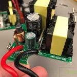
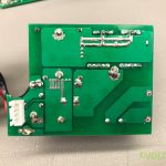
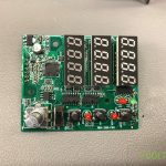
Welcome to a new Voltlog, today I’m gonna be showing you revB for the ESP32 based thermostat valve controller, this is based on revA that I first showed in Voltog #383. So a few words about this board, just in case you haven’t seen Voltlog #383. It’s based on an ESP32 and I designed it so that it’s compatible with the open source firmware called TASMOTA and that allows us to control it via MQTT from homeassistant.
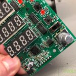
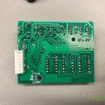
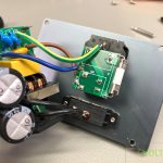
We have 10 individually switched triacs, each capable of up to 900mA or 1.2A depending on the version of the triac that it’s equipped with and a few expansion capabilities via I2C, 1Wire and some spare GPIOs. Everything was designed to fit inside one of these inexpensive, DIN rail enclosures and the whole purpose of this is to allow smart control of electrical thermostat actuators.
In my case, I use these 240V rated electrical thermostat actuators to control zone valves for my floor heating system. but if you would like to know more, I recommend you also watch Voltlog #383.
So why did we need revB? Well I’ll tell you all about the changes that happened in revB and I’m gonna start with this odd shape that you see around the ESP32 module, I removed the PCB from under the antenna section of the wifi module and although the improvement is probably marginal, in theory at least, it helps to keep the antenna clear of other objects.
Let’s start the mailbag with this tiny PIR motion sensor switch. This little guy is rated for 12V up to 2A load so it’s got an input, you supply 12V to that and it acts like a switch for the output with a 2A load capability. It comes with these connectors witches makes me think it’s meant to be used as part of led installations, maybe for custom furniture or cabinets because it has this mounting bracket and that’s probably how I am going to use it, to light-up this warm white LED tape that I have built into a piece of furniture. This is rated for indoor use only so don’t go using this outdoors as water will get in and corrode the electronics inside. Same as usual links for all of the items shown in this video will be placed in the description below and while you are down there, why not smash that like button, because it really helps increase the chances of this video being seen by more people, it’s just how the algorithm works.
Next up I got some transparent heatshrink, I needed some of this recently so I got two different thicknesses, Sometimes you just want to be able to see through the heatshrink part or you might just want to insulate some metal rod without adding any color so the easiest way to do that is to use some transparent heatshrink.
Welcome to a new Voltlog, in this video we’re going to talk about oscilloscope differential probes and what I have here is the Micsig DP10013, this is a 100MHz differential probe that will probably help me not blow up my oscilloscope when probing high voltage stuff like inside a switch mode power supply.
But first a full disclosure, this unit was provided for free by bangggood.com for the purpose of this review and if you decide you decide to get one after watching the video check out the link I’ve placed in the description below, there will also be a discount coupon that you can use to get the Micsig for a better price.
So as usual with Micsig instruments they do come in these nice plastic carry cases, I mean they are not super high quality but certainly decent and certainly nice to have such a carry case for protection during shipping and for storage purposes.
Inside the carry case, we get the differential probe itself, a USB cable which is branded Ugreen, that’s actually nice to see, Ugreen makes good quality cables. If you’ve seen Micsig instruments before, you now they don’t use any batteries, they are powered over a USB port and that’s super useful and appreciated because this is the type of instrument that you will not be using everyday, this will mostly stay stored in it’s carry case for month before being used again and guess what happens when you forget about those batteries? Yeah they leak and they corrode the inside of your test gear so I very much like the fact that it doesn’t use batteries.
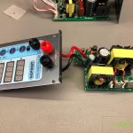
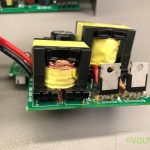
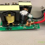
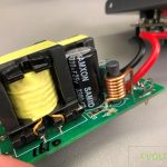
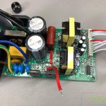
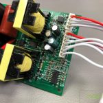
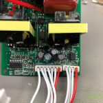
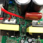
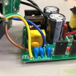
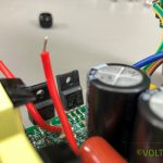
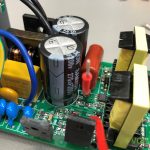
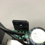
Welcome to another power supply review video, today it’s about the Gophert PPS-1610, I’m not sure how new this model is, I don’t know the exact date it came out but it’s fairly new and full disclosure this has been sent to me for free for the purpose of this review by a seller on aliexpress so should you decide to order one of these, there will be a link in the description below.
You may know I am a big fan of Gopher power supplies, I have like 5 units on my bench and they are generally my preferred way of powering stuff around the bench, unless I’m dealing with super sensitive analog stuff in which case I’m probably using my old trusty HP linear power supply. The gopher power supplies have been super reliable, for example I have been using my first one since 2015, that’s 6 years of usage already, I have subjected that power supply to multiple assembly/disassembly cycles for various teardowns and reverse engineering and to various noisy and spikey loads and full load conditions it just hasn’t failed me so far.
Welcome to a new Voltlog, in this video I’m gonna talk about the new CanLite revision D which is now ready to be ordered on my Tindie store and you’ll find a link to my Tindie store in the description below. Yes I am already at rev.D for these boards and that’s partly due to the ongoing global chip shortage which forces me to switch to a different switch with every new batch that I manufacture but I’ll get into that later, first if you don’t know what CanLite is let me tell you a few words about this board.
The idea for this board started back when I first experimented interfacing with the CANBUS for various automotive modules like the instrument cluster, the CAN gateway. The parking sensor module, the multimedia, I wanted to see what kind of messages get transmitted on the CAN bus network, if and how I can intercept and modify those or maybe insert my own messages so basically hacking on the CAN BUS network of my car.
I did a whole video on the subject a year ago voltlog #342 which I will link on screen if you haven’t seen that and you’re interested in the subject check it out.
So I wanted to create this little board that could be installed in a car and perform various functions on the CanBus, I chose the ESP32 as main processing unit because that’s plenty of processing power for the task on hand, it’s also cheap, it has wifi and built-in CAN peripherals so it was a logical choice for me to use it.
I still needed to add an external CAN transceiver to generate the differential voltage levels for the actual physical link and while I was there I also threw in an automotive grade buck regulator and a couple of automotive grade high-side switches just in case I needed to switch a load, something like a light or a motor, or whatever you might need cause these automotive high-side switches are pretty robust and you can drive pretty much anything you want with them.
And this brings me to the reason for revD, I’m sure you are aware of the ongoing global chip shortage and how car manufacturers have to stop their manufacturing plants because they can’t get the chips they need.. Well, guess where that left with my automotive high-side switches and automotive-buck regulator?
Yeah not a great choice of parts when it comes to availability, I mean, January 2023? That’s like 14 months away just for the buck regulator, all while people keep emailing me constantly to ask about the availability of the CanLite boards. The same thing could be said about the high-side switches I was using, they couldn’t be found anywhere and that’s not the only problem.
You can hardly find any alternative parts either, I’ve spent hours and hours trying to find replacements on Digikey and mouser and all I could find is low stock of parts that cost 10 times as much and come in much larger packages, but in the end my efforts paid off and I managed to find these, the BTS452T from infineon and although these have a lower maximum switch current, I had to settle for these, I mean 1.8A per channel is still plenty of current to be useful and we still get the nice features like over temp protection, over-current protection and general transient protection that these automotive switches feature.
I also had to go for a new inductor, which was slightly different, because that wasn’t available in stock either and don’t get me started on the lack of standardization when it comes to these surface mount inductor package, it’s like every time I need to use an inductor I also have to design a new footprint cause they are never the same exact size.
Welcome to a new Voltlog, in this video I will show you how I assembled this VFD tube based clock, I like the looks of this clock very much it’s kind of steampunk type of style and because this is a kit, it’s widely accessible to anyone, you don’t need very specific tools to get this assembled and I believe anyone can put one together. As a bonus this clock, although it doesn’t include one in the kit, it can support connecting a GPS receiver for syncing the clock and on top of that you get a remote control so you can control it from a distance which is pretty neat if you ask me.
I got this particular kit from banggood and you’ll find a link in the description of the video if you are interested in getting one, I think it’s important to watch this video before you start the assembly because you might find some inadvertencies between the provided user manual and the actual kit that you receive.
This is what you will receive in the box and this is pretty much all needed for a functional clock, if you are missing the stuff shown here you might be unable to complete your clock build. Like I previously said the GPS module is optional but depending on where you live you might not get GPS reception in an apartment building for example so it might be useless to you anyway.
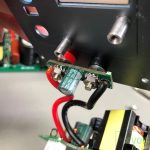
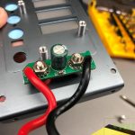
Welcome to this short Voltlog where I plan to take a look inside this JBC clone soldering iron handle. This is the handle that came with the Best-933B JBC clone station, I reviewed this in Voltlog #340 a year ago and I’ve been using this station as my main soldering tool for the past year. I plan to do a future video where I tell you my opinion about this station after 1 year of usage but the short story is obvious due to the fact that it’s my main soldering tool, I like using it.
The soldering handle that I received with this station had a problem since day one, first use, when I inserted the soldering tip into the handle I could kind of feel like there was something wrong, there wasn’t a clear stop when pushing it in and after powering on the station the screen was flickering, it couldn’t read the temperature and this cable got hot which is a good sign that something is shorted inside the handle.
I’m not sure if I am to blame because I might have pushed the tip too hard into the handle the first time. It’s also possible that it had a factory defect inside the handle.. Other users of this station don’t have this problem but long story short ever since I got it, I had to be really careful when switching tips because I needed to seat the tip very accurately in a certain position, otherwise it would short circuit causing the station to go crazy.
Welcome to a new InTheMail, the series that will touch both your passion for electronics and your bank account at the same time. Checkout the items I received in this mailbag which include: raspberry pi CM4 heatsink, Mains powered PIR sensor, Parachute cord mini carabiner, Nylon tactical mini hook, DIN rail enclosure, transparent din rail enclosure, Dremel tool key, Drilling dust collector, OV2640 camera for esp32-cam, Molybdenum diamond wire, 50ohm in-line BNCload.
Welcome to another Voltlog product review and in this video we are taking a look at the DytSpectrumOwl PCB thermal camera and let me tell you from the start that if you do a lot of PCB repairs or if you do any kind of product thermal characterization, your life would be so much better if you’ve had a tool like this and I’ll show you why in a few minutes.
The company that makes this product is DianYang Technology and I guess the name of the product is DyTSpectrumOwl model number CA-10, this is a 260×200 pixel resolution IR camera sensor with a 25 fps refresh rate and manual adjustable focus lens which allows it to focus from 20mm up to 2m, that 20mm close range focus and the 25hz refresh rate are very interesting features and I’ll talk more about that in a second.
I received the unit very well packed in a double cardboard box and all I have to do is to fix the vertical stand to the base and attach the camera. While doing this I couldn’t help to notice the very good construction quality, they’ve used anodized aluminium and metal parts everywhere, everything is nicely machined, rounded corners, really nice attention to detail, like for example , the work surface has an insulating rubber coating which would prevent shorting something on the PCB you are testing and on the bottom side they have nice rubber bumpers to prevent it from sliding around. Inside the box they include a small screwdriver that you use for attaching the vertical stand to the base, a couple of spare screws and a USB type-C to USB Type-A data cable.
Camera has a USB Type-C interface, looks like the shell is made from plastic and painted the same metal gray color and you get a single on/off button with a status LED on the top. On the sensor side you get this big focus adjustment wheel and we’ll play with that later on when we get to look at a PCB but since we are talking about PCBs let me introduce the sponsor of this video
Raised to its maximum setting, you get about 15cm of clearance between the work surface and the camera and that’s plenty if you ask me and you also get the option of moving the stand to the left of the work surface by using these mounting points. There are a few adjustments on the standm you can raise or lower the camera by sliding on the vertical rod but you can also do fine adjustment with this thumbwheel at the top. Then you can move back and forward from this adjustment and you can also adjust the angle of the camera so you can pretty much get this into every angle you want but I would probably use this looking straight down at a PCB.