Voltlog #280 – TPS62840 olmBoard Ultra Low Power Step Down Converter

Welcome to a new Voltlog, in this video we are taking a look at the TPS62840 ultra low power step down converter from Texas Instruments. It’s basically a buck converter with an input voltage of 1.8-6.5V, 750mA output current, with a quiescent current of just 60nA and active current of just 120nA. It also features very good efficiency at light loads of just 1uA it can offer 80 percent efficiency.

Other features include 16 selectable output voltages through an external resistor and a stop pin which when activated will completely stop any switching to eliminate any switching noise for a short moment, allowing you to take for example an ultra low noise measurement during that time. During that take power will be sourced from the output capacitors. So it looks like this is a pretty interesting dc-dc converter, with really nice features and it’s optimized for ultra low power devices.
Voltlog #253 – Aneng V01A Multimeter Review & Teardown

Welcome to a new Voltlog, today it’s a multimeter review because we haven’t done one in a while and here I have the Smart Digital Multimeter which sounds like a generic name, no obvious branding on the box but granted it is featuring the multimeter on the box, it’s a color image which is not often seen on these cheap meters. On the back, the meter is shown in full black holster and we get a model number sticker, AN-V01 so this probably indicates the Aneng brand.

We’ve looked at Aneng multimeters in the past in Voltlog #114 and others and I’m gonna say this again, Aneng does not make multimeters, Aneng is just a company that rebrands existing multimeters made by other companies.

Voltlog #246 – What if we install a heatsink on the TPS61088 boost module?

In the previous video where I took a closer look at the TPS61088, I did some measurements of the output noise but I also ran the module up to the maximum specified output power of 12V 2A. It was to be expected that the losses would turn into heat and just the small size of the board would not be enough to dissipate all that heat safely so the boost chip reached a toasty 150 degrees Celsius and inevitably went into thermal protection.

There were two questions that people mainly left in the comments of that video. First people were curious if this module would behave differently if a heatsink was installed and also some people thought about using this module in a fixed configuration, because if you remember there is a chip on this module that will switch the output voltage based on quick charge spec, depending on what the load is requesting through that protocol but people might just want a simple fixed output. To this I would add a third question of my own, what is the real efficiency figure of this module, at the maximum output. 

Voltlog #245 – TPS61088 Boost Module Test (with QC3.0)

The real limitation for this small module to output the claimed 24W for longer periods of time is temperature. There is not enough thermal dissipation happening with this small pcb. Having a bigger pcb with more copper layers would help and it would probably allow this module to output continuously and prevent the TI controller chip from going into thermal overload. Even so I was impressed that running it into thermal protection several times did not do any damage the chip recovered on it’s own each time and no magic smoke escaped during these tests.

So all of this considered, this is probably one of the best dc-dc boost converter modules I got from China so far and I would recommend getting one of these if the specs meet your needs.

Voltlog #132 – 4 Digit LED Panel Meter Review

Do I recommend getting this module? Yes, the accuracy is good, the resolution is nice 10mV 1mA and you also have the option for adjusting it manually for both voltage and current.

The design is pretty simple, I believe the microcontroller is an STM8S so hacking it and rewriting the firmware should be pretty easy but it already does what it’s supposed to do so I don’t see a point to hacking this module. I think you would be better off designing a panel meter from scratch.

Buy this panel meter from here.

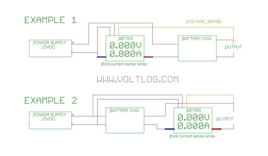
Someone asked on youtube how should a panel like this be wired up, so here is a wiring diagram that you can use. In this wiring diagram our goal is to monitor the voltage and current for charging a battery.

Example 1 shows the panel meter connected before the battery charging module, which means it will measure everything, even the power losses in the battery charging module.

Example 2 shows the panel meter connected after the battery charging module, which means it will only measure current flowing into the battery or whatever load you have on the output.

In both cases voltage sensing is done right at the output but that wire can be moved according to your needs. Also in both cases the panel meter gets power directly from the power supply because at that point the voltage is constant.

The main thing to remember here is that these panel meters are designed for low side current sensing, that means the ground of the logic board of the meter is connected with the input of the shunt resistor.

Voltlog #128 – LM338 Constant Current Regulator Circuit

Welcome to a new voltlog, today we are building a very simple constant current regulator based on the LM338 linear regulator. This is a very robust and stable classical regulator that is being manufactured by many big names like ST and TI, it has quite a high output current  rating of 5A continuous, it even comes in a TO-3 can package but today we’re going to use a TO220 which is more commonly available.

To make a constant current regulator out of this, is very simple, the datasheet gives us the circuit we need to use and we only need a low value resistor to do that plus the optional input bypassing cap which is 0.1uF. We’re going to use this formula to calculate the value of the resistor, so the output current is equal to the Vref divided by the value of the resistor.

External references:


Voltlog #127 – 0-60V 0-10A 1mV 1mA Panel Meter Review

So I discovered this module a few months ago and it’s been sitting in a box since then, I almost forgot about it, until a few days ago when I decided it will be a good idea to do a video on the subject.

Let me give you a few details on the specs of this module and as usual it’s pretty difficult to find the information as it’s the case with every new module coming out of China. First of all we have an input range of 0-60V and 0-10A and a 5V rail is needed to power the module itself. It has a voltage measuring accuracy of ±0.2% + 0.2% full scale which sounds strange because these figures are usually given in a percentage plus or minus a number of least significant digits. The current measuring accuracy is ±0.4% + 0.3% full scale.

The meter is basically capable of measuring with a resolution of 1mv and 1mA (however the accuracy is quite bad, as shown in the video) which is quite nice and useful (not really useful with bad accuracy) for projects like DIY power supplies or DIY electronic loads. It can also display the power in watts with a resolution of 1mW as well as showing the load impedance.

Here are some links to this product: