Welcome to a new Voltlog, today we’re comparing a few different serial to usb adapters and the discussion started ever since I showed the CH340E breakout board I designed in voltlog #249. People wanted to know if this CH340E affordable chip would perform similar to the well known FTDI or Silicon labs chips, and I’m thinking at high throughput and reliability here, the kind of application where you are sending lots of data, fast and you need it to be transferred reliably.
So today I’m going to compare the CH340E with a CP2103, and the FT232RL. I wasn’t sure what measurements to take and how to test these but I devised 2 testing methods.
Welcome to a new Voltlog, today we’ll have a little chat on IPA cleaning wipes. Professional PCB wipes soaked in IPA are pretty expensive and hard to get but can we substitute those with something cheaper that works just as nice for cleaning the flux residue from PCBs?
In this video I’m gonna show the second revision of my esp32, battery powered PIR motion sensor. This second revision contains some optimizations to improve deep sleep power consumption as well as to fix some of the errors I had the first revision of the pcb.
Welcome to a new Voltlog, those who have been with me since the beginning of this channel, may know the first video I ever released, Voltlog #1 was a review of a switch mode bench power supply from Gopher Technology. It was the CPS-3205C and it was a great little unit, it has served me well over the years and I still have it.
At that time I complained about the fact that the unit has the output jacks on the back which is not really convenient for bench use. There were also other issues mentioned while measuring the performance of the power supply, I will link that video on screen if you want to watch it but the video, audio and editing quality are lower than what you’re seeing today.
Gophert made some improvements to the original design and have now released a newer version of that power supply, it has a new model number it’s NPS-1601 but it’s the same range of 0-32V and 0-5A. There are other models with different ranges but this is what would correspond to the CPS3205 I reviewed years ago.
They have made a bunch of changes on the front panel, the most important one is they moved the output jacks to the front panel so now it’s easier to connect the output of this power supply but they are still not standard spacing so you can’t connect one of these adapters with banana jacks. They have also redesigned the front panel completely, they are still using 7 segment displays but now they also have a wattage display which can be switched on temporarily in place of the amps display, you press the watts button and it will show watts measurement for about 3 seconds before reverting to amps display.
The switch for A/V adjustment is now tactile instead of a sliding switch but the rest has stayed the same. I like this redesigned front panel I just wished they used a lighter color for the text, because for example there are some markings which are barely visible next to the LEDs.
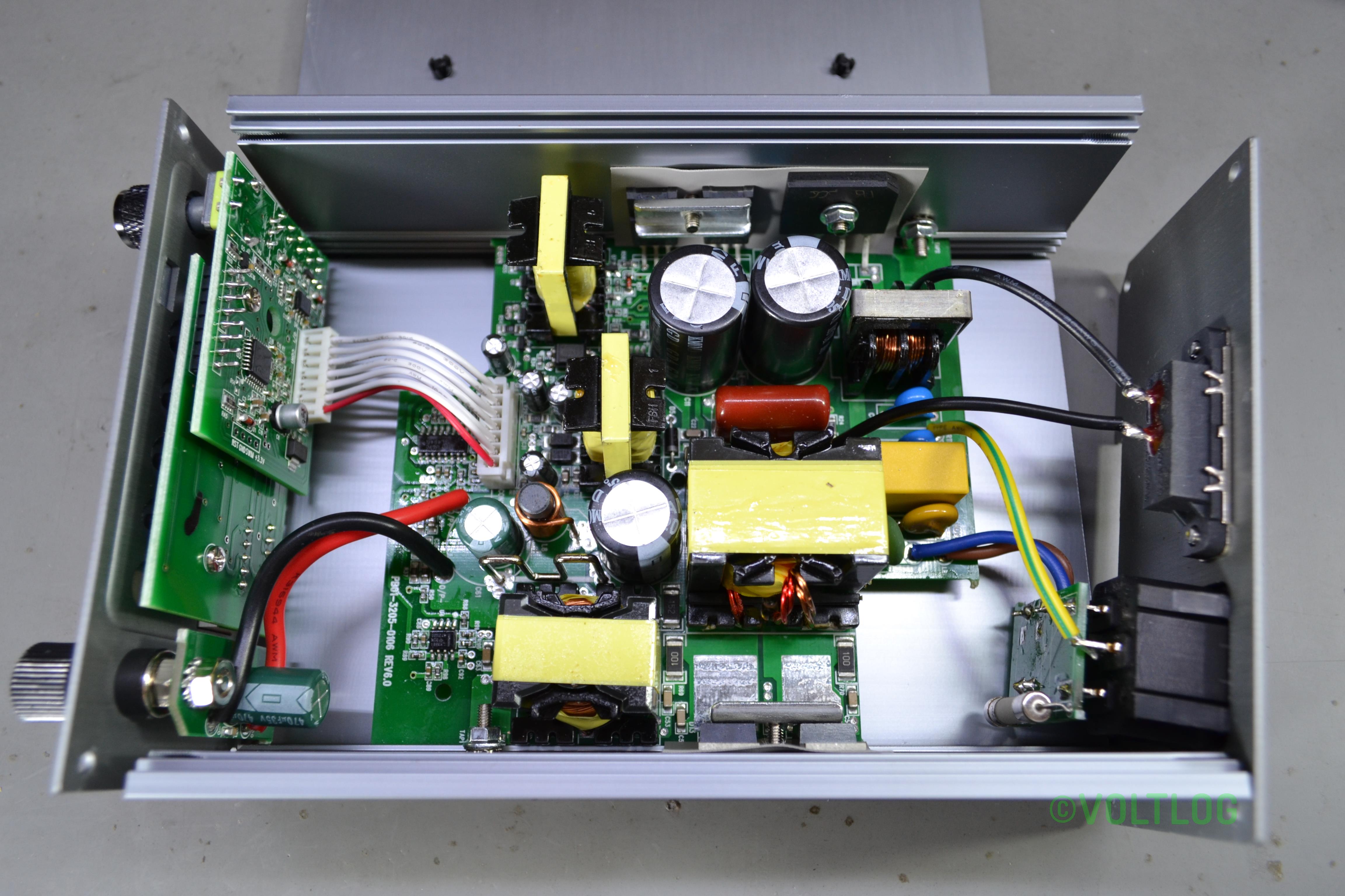
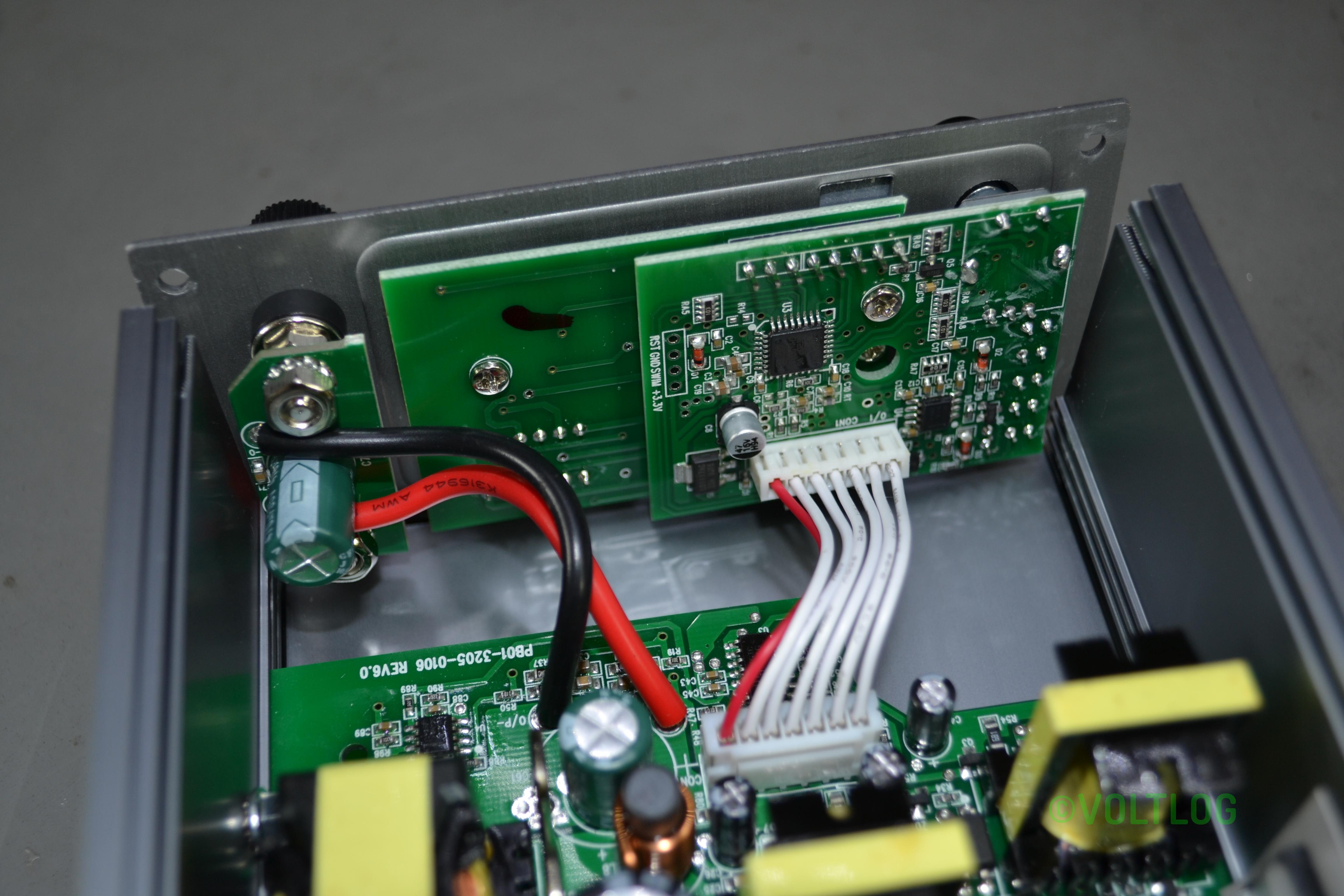
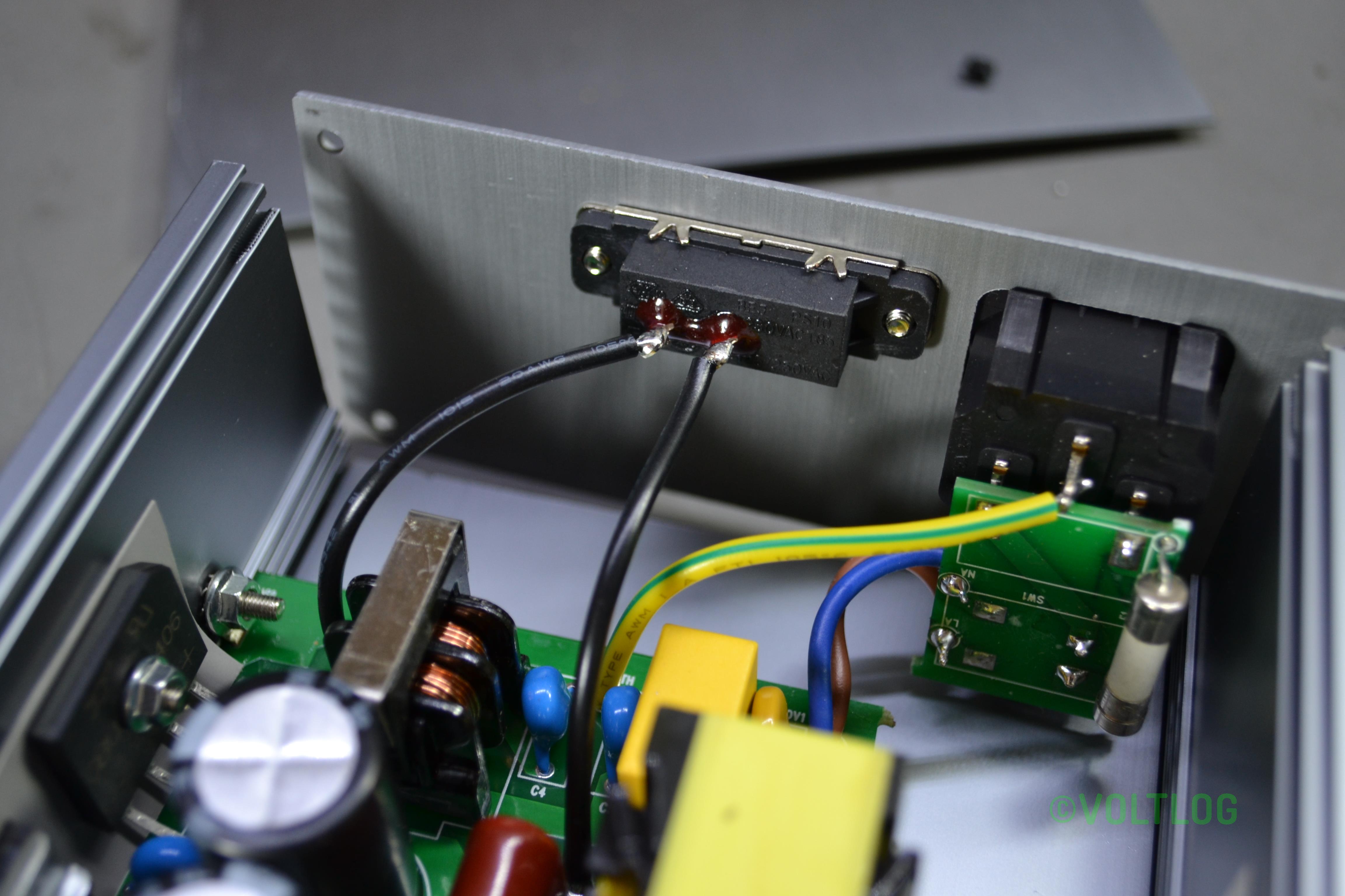
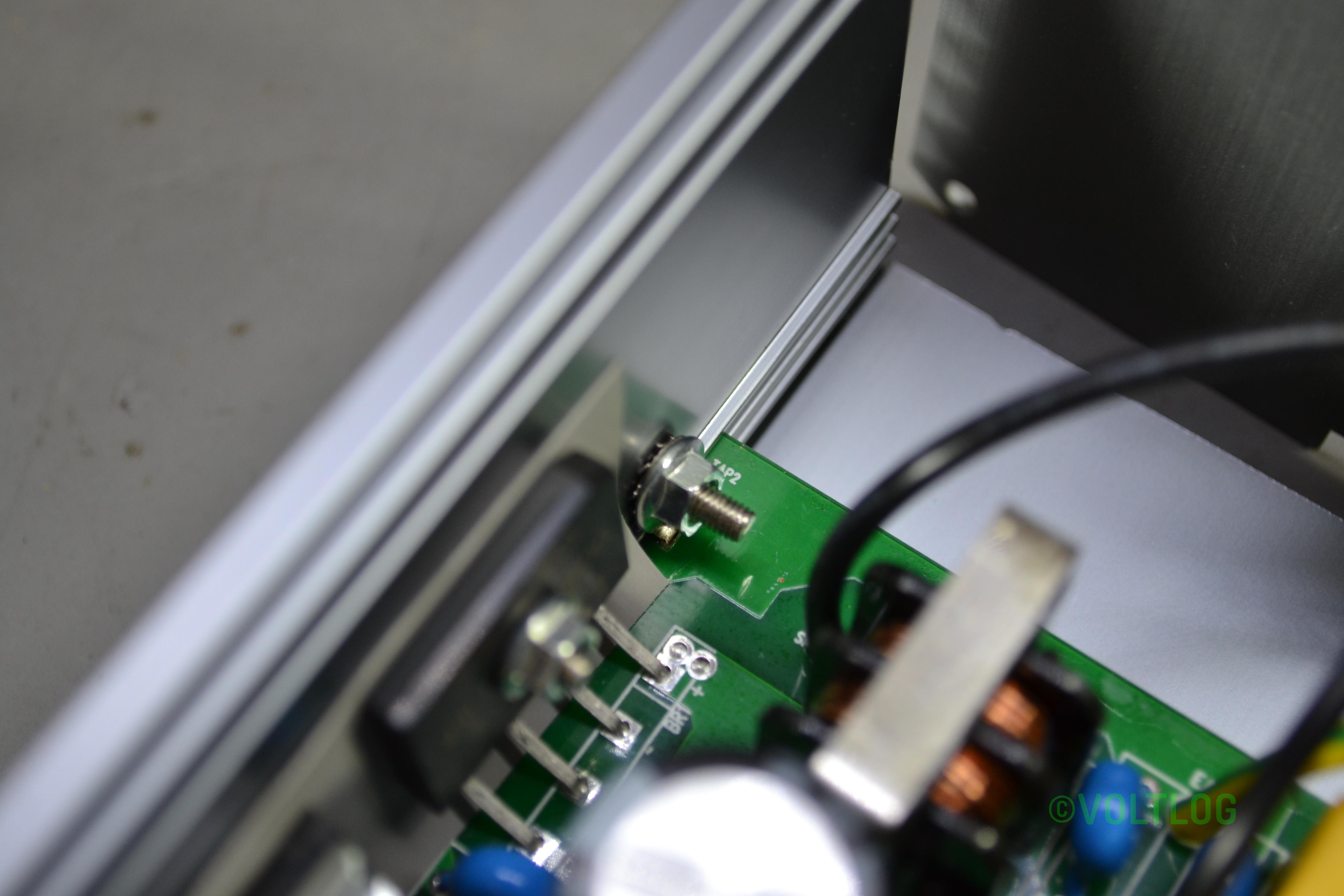
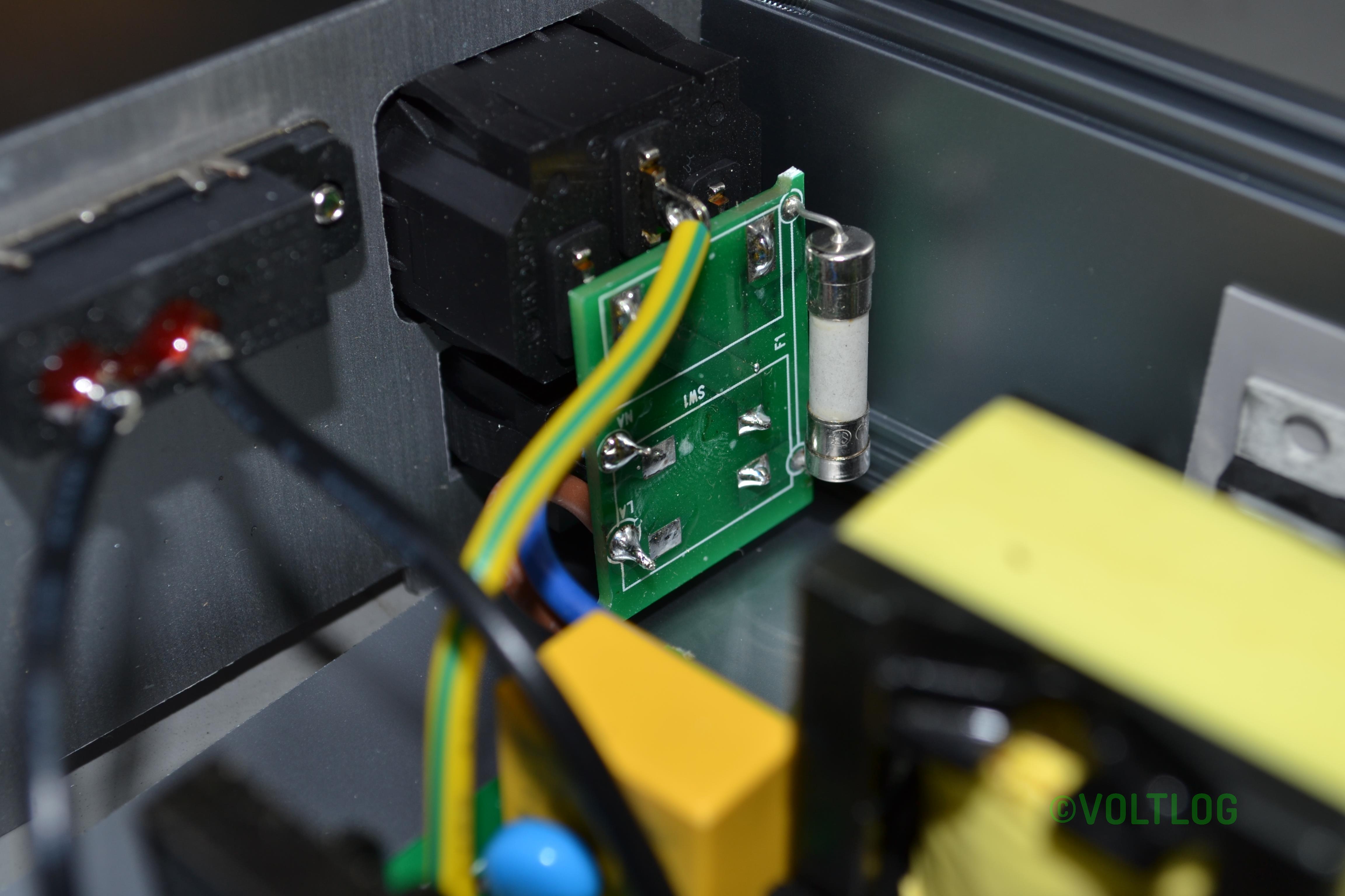
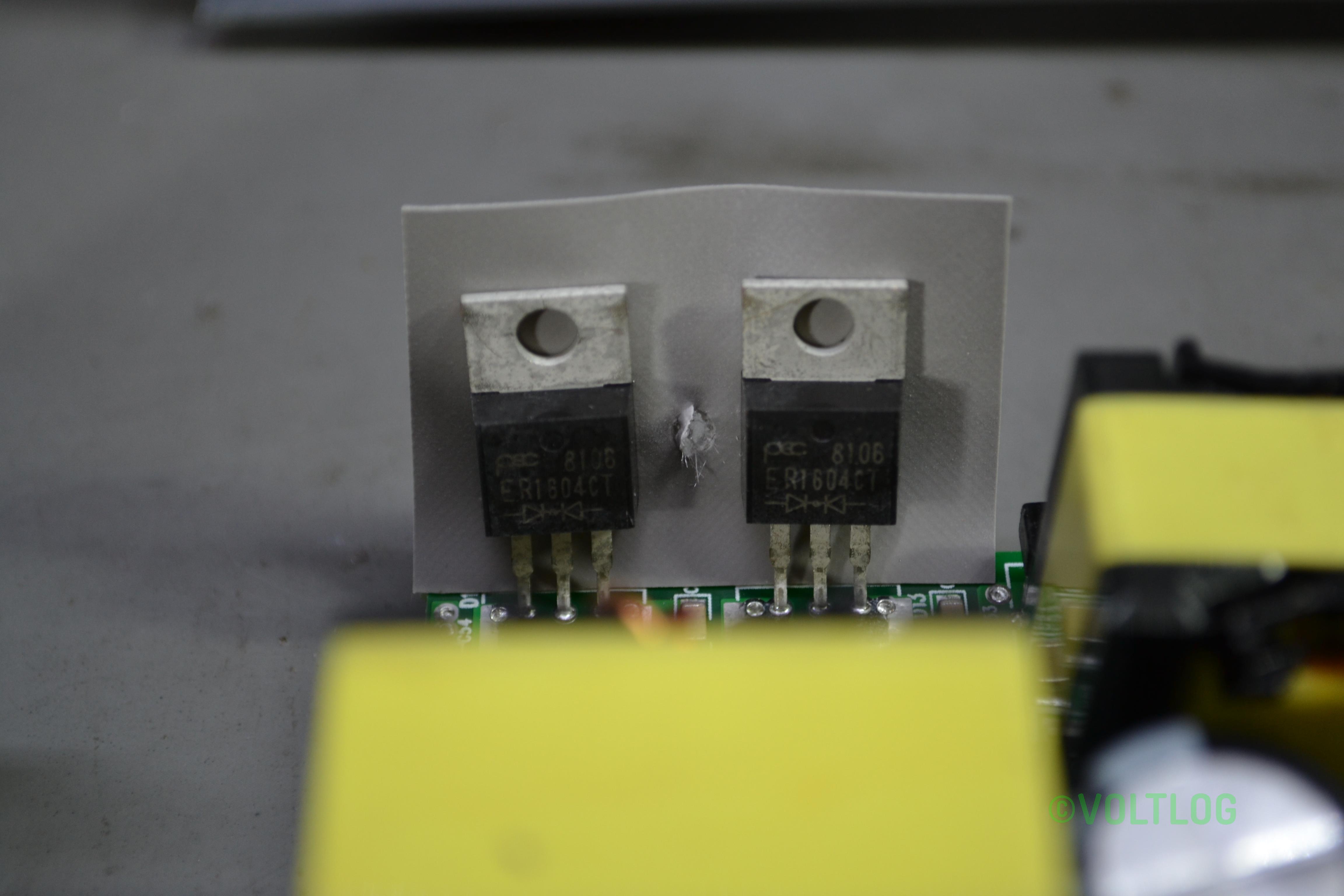
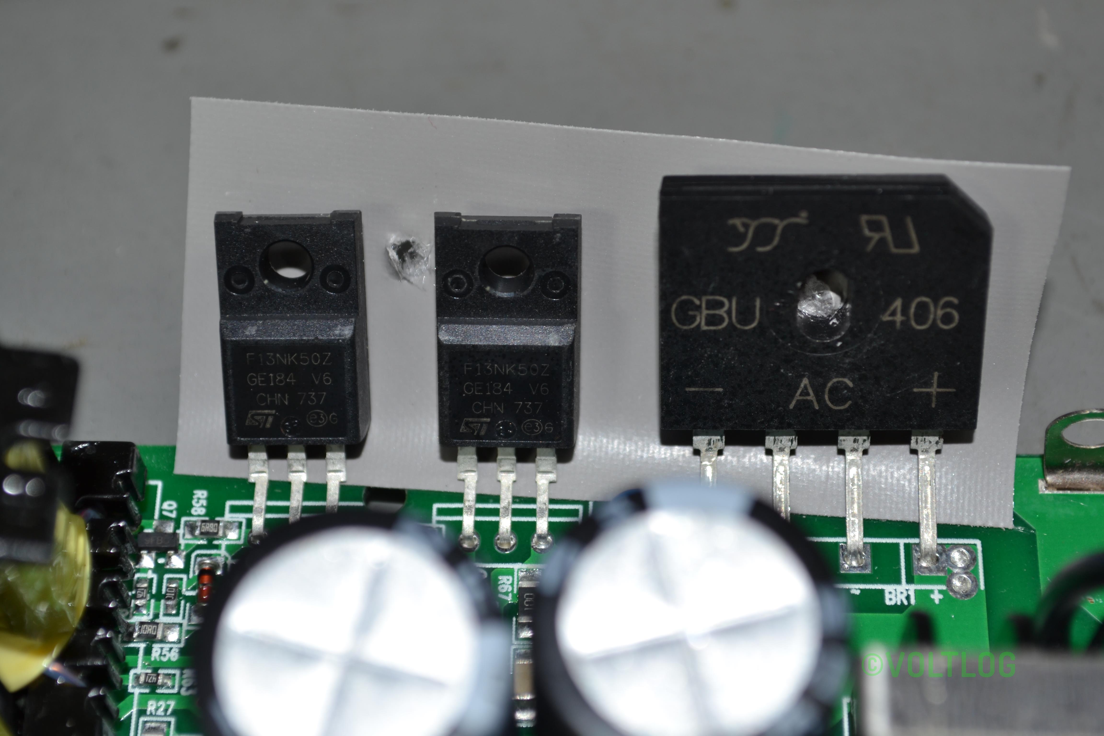
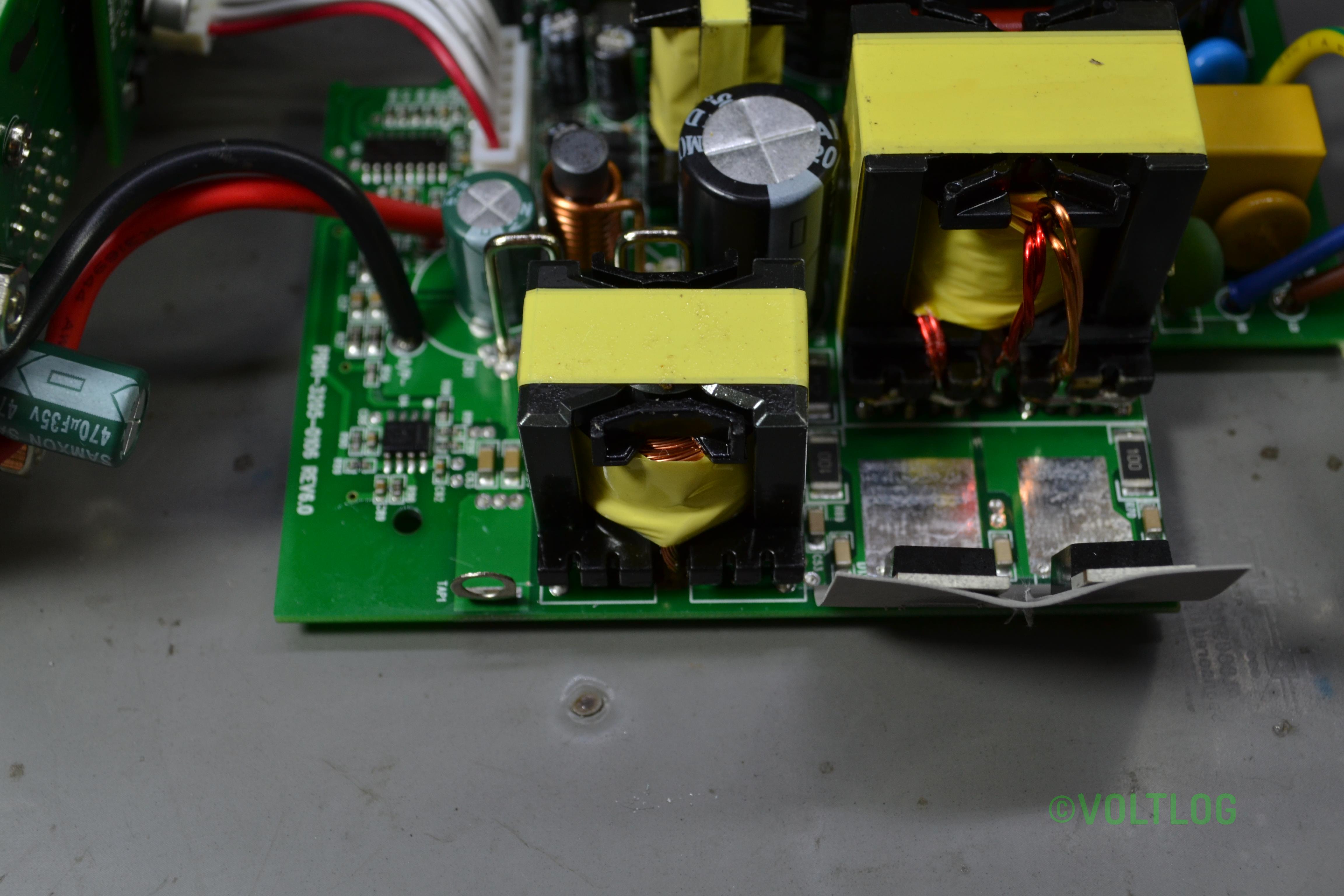
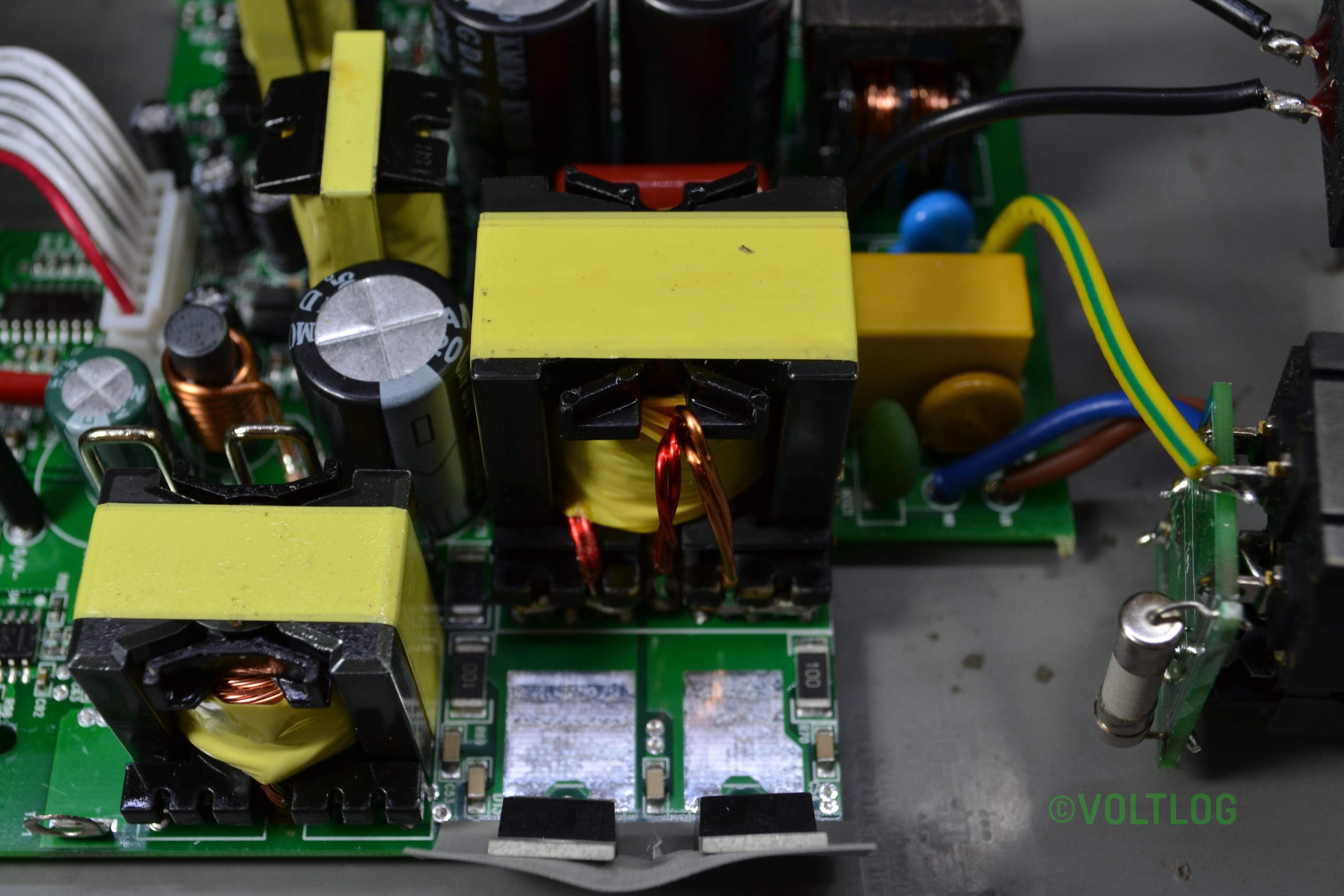
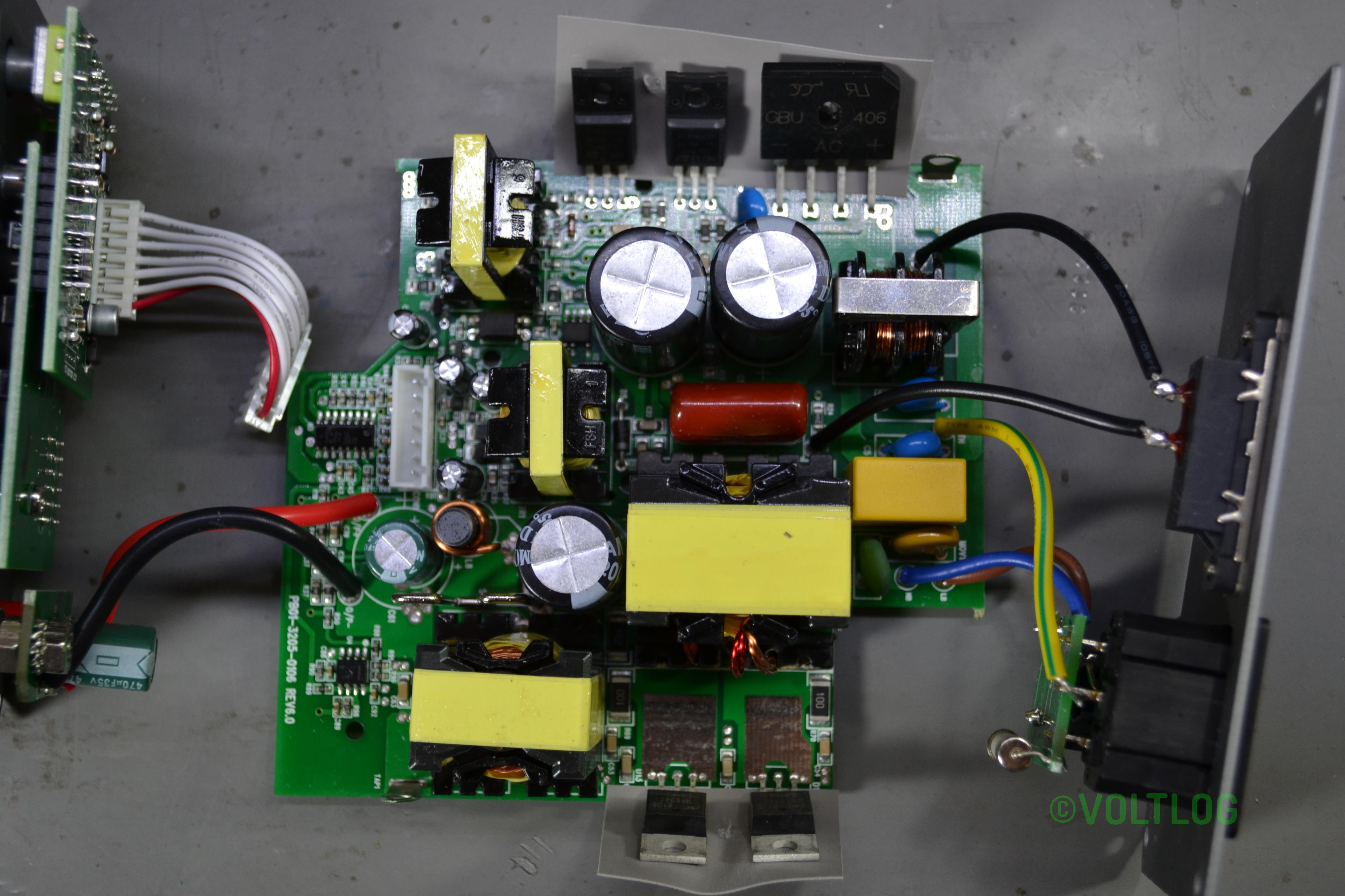
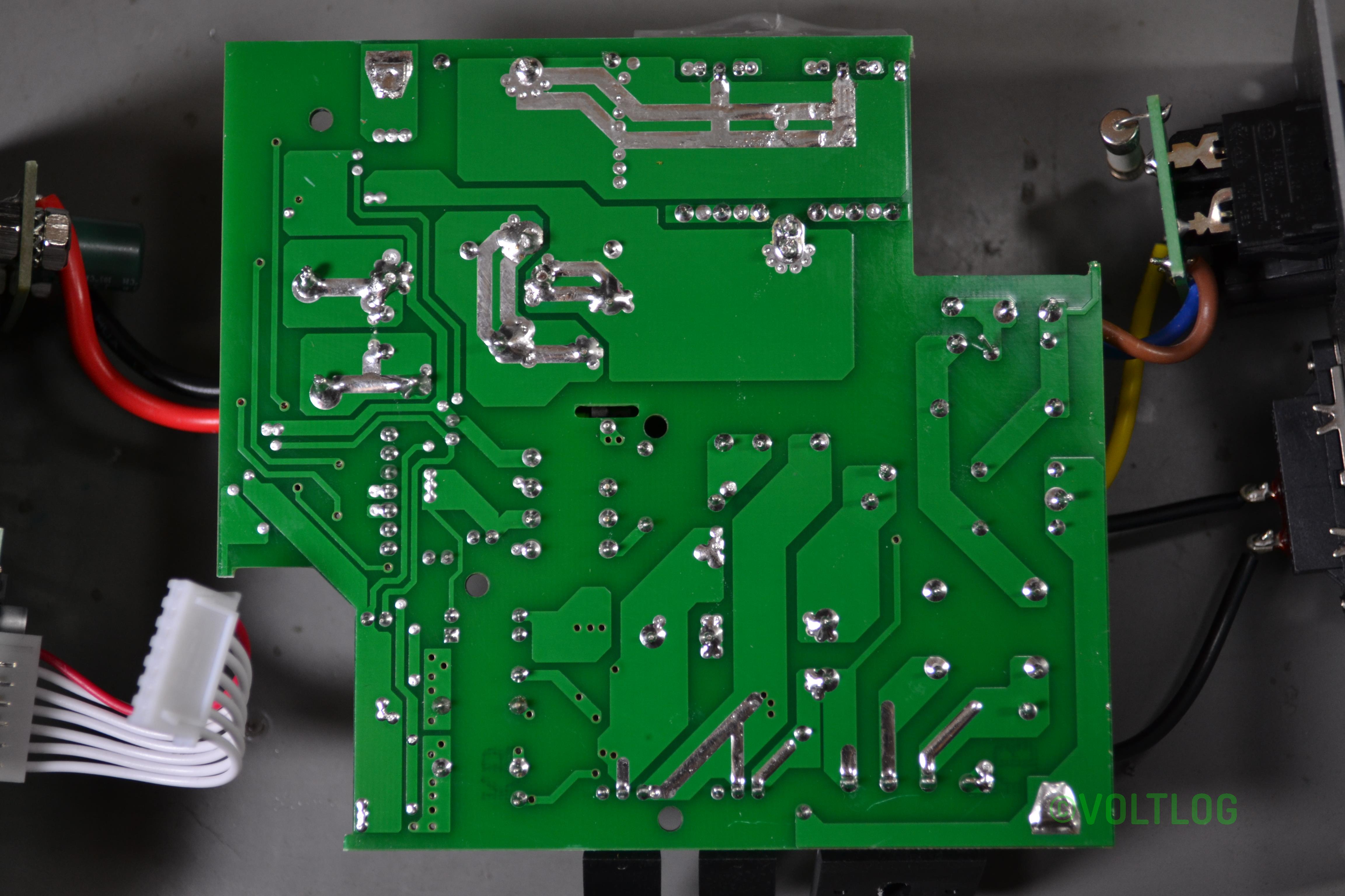
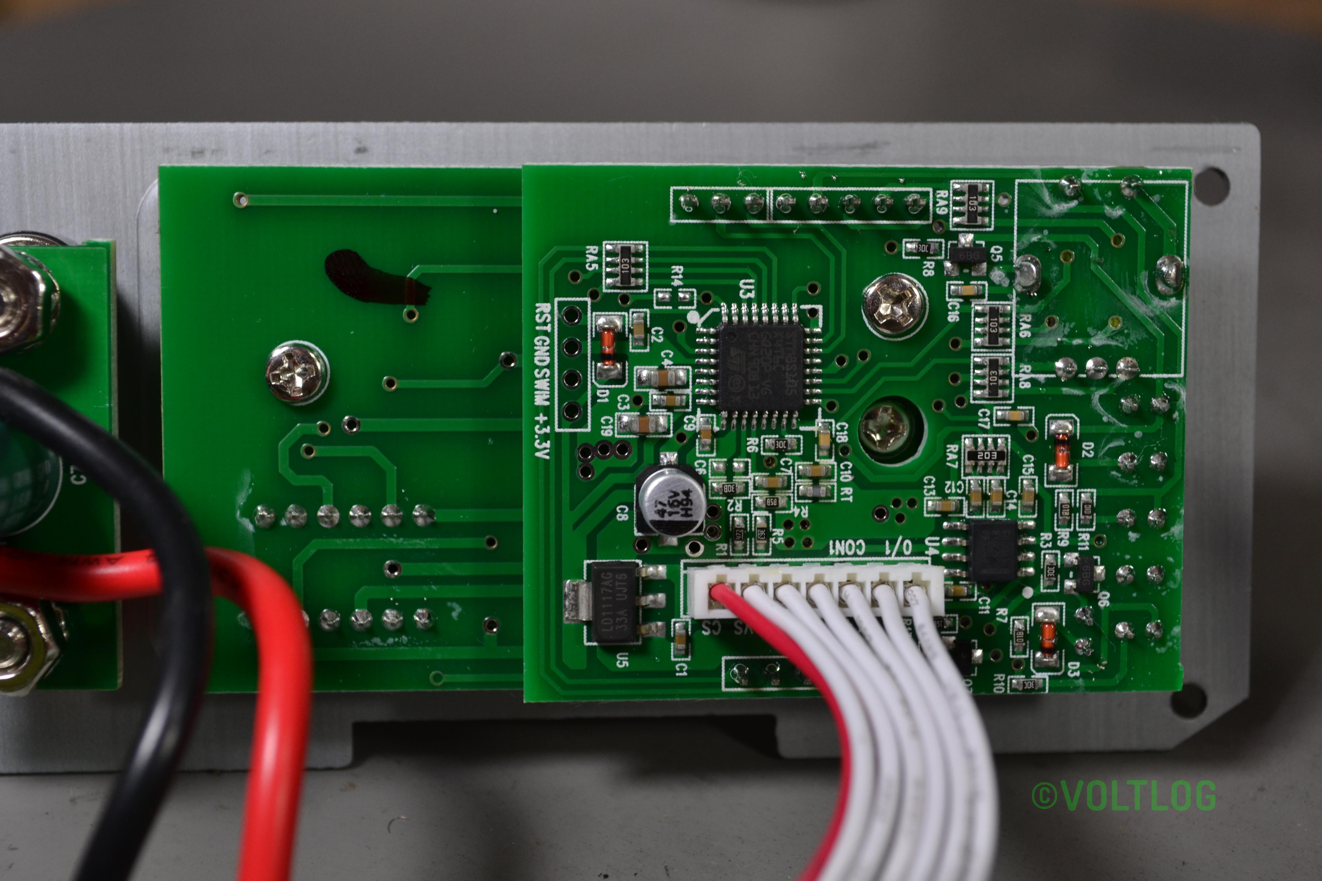
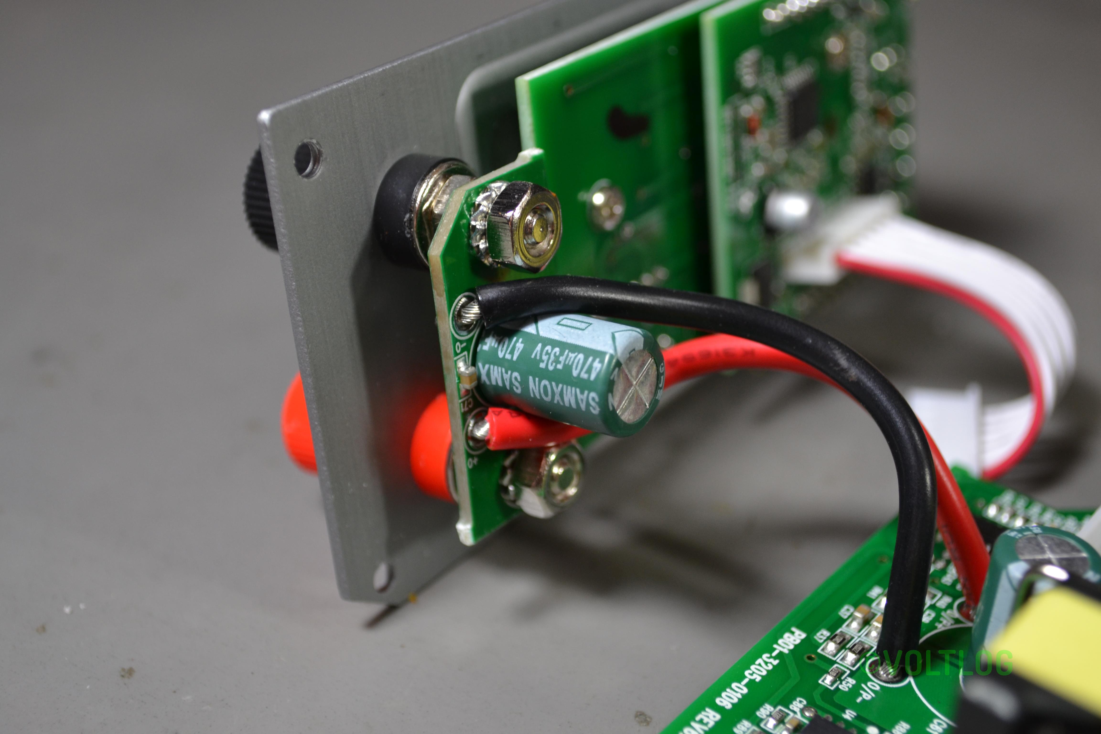
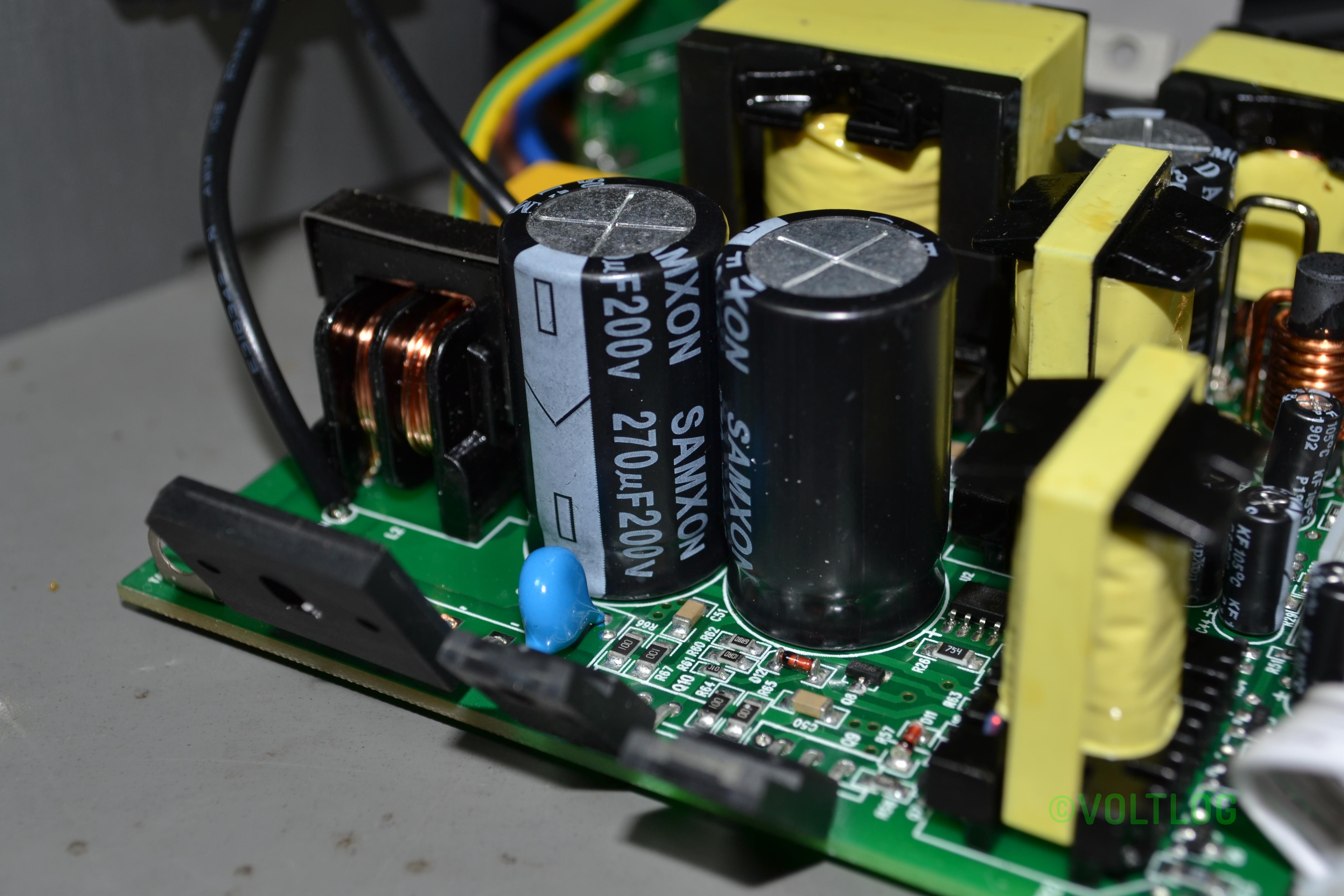
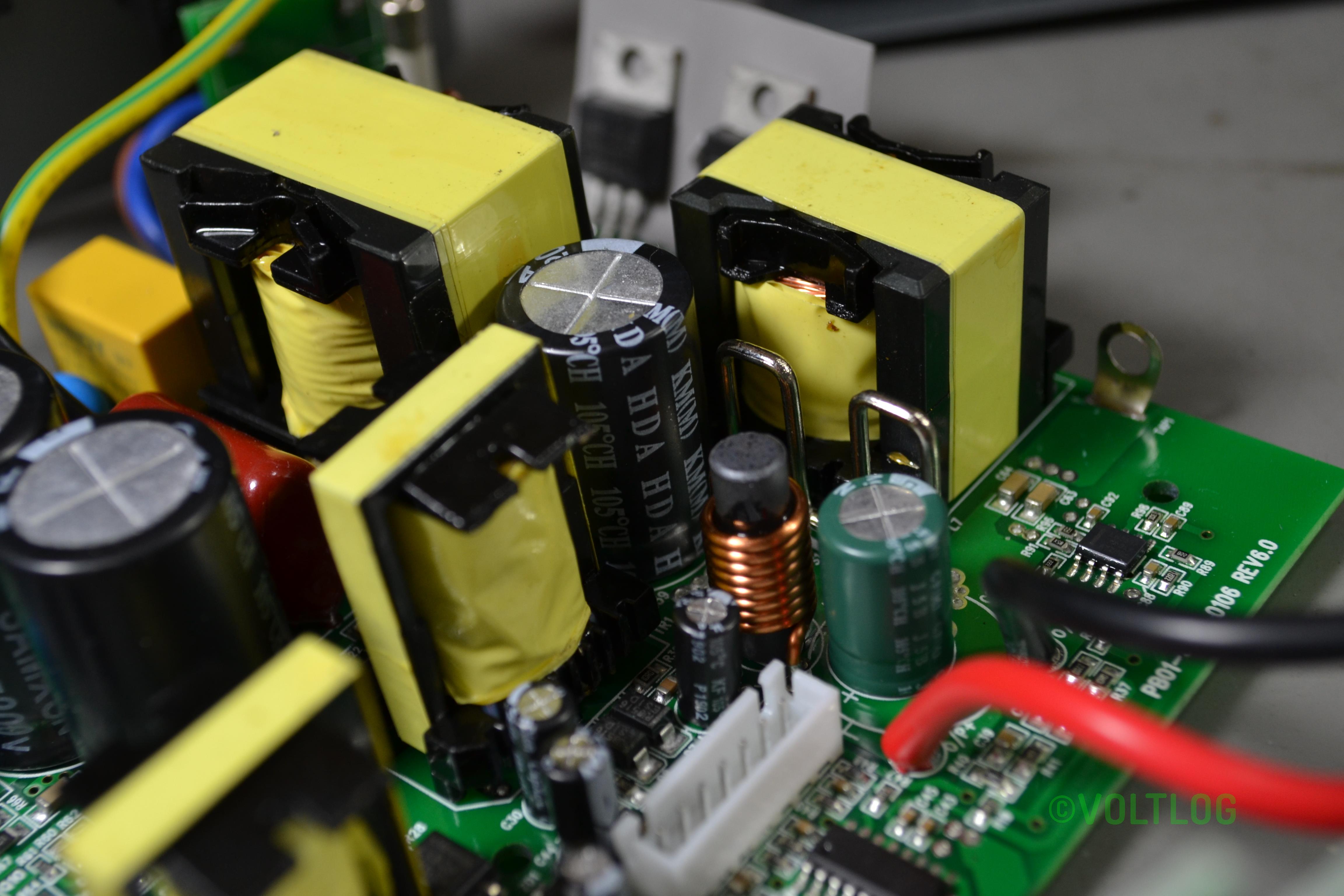
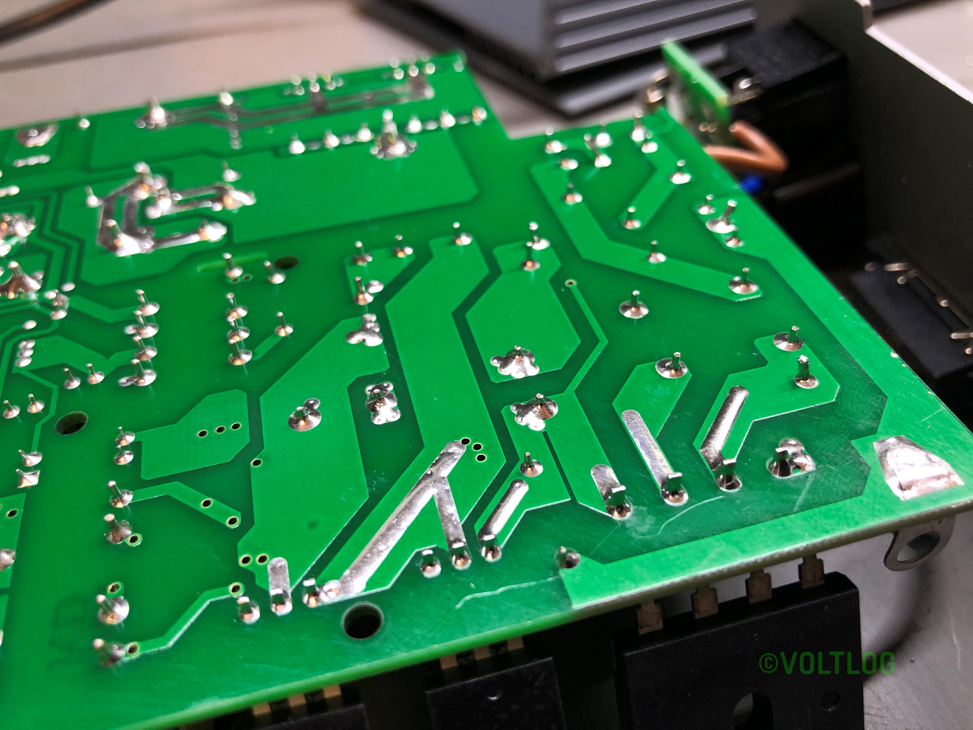
Here is a set of pictures I captured during the teardown:
Welcome to a new voltlog, today we’ll have a little chat on epaper displays. You probably saw this post I made to my youtube community page a few days ago, it was about my epaper thermometer which suddenly showed the low battery sign and stopped working. I’ve only had this running for 1 month, when I received it, the battery was not connected so I thought it must have been an old battery or a bad one.
Welcome to a new Voltlog, in this video I’m gonna show you how I designed and built this board which functions as an esp32 based, battery powered PIR motion sensor. So I started by designing the circuit, I used some common building blocks, I added the ESP32 with it’s bypass caps, some test points and the programming circuit with auto-reset, I then added some connection points for the PIR sensor, an RGB LED because why not have a nice way to signal this is one of those very small digital RGB leds, it’s just 20x20mm, it’s connected to 3.3V even though it’s only rated for 5V so I’m hoping this is going to work even on 3.3, it’s also worth having a temperature/humidity sensor to also sense that in whichever room the node will be placed and finally the power supply circuit which is a simple low dropout regulator with an 18650 battery as the input.
I did not include a battery charger circuit on this module, because I wanted to keep things simple, I’ll have a battery socket so I can just remove the 18650 cell and charge it separately plus the whole circuit should run in sleep for extended periods of time giving me a long operating time so i wouldn’t have to charge the battery too often.
Once the schematic was finished I did the board layout in a hurry so it’s not exactly pretty or optimized
but I tried to move the esp32 antenna to the side, to place the PIR sensor in the top side as the module will probably sit vertically, I tried to place the temperature sensor in the bottom side to keep it away from any components that might get hot and also placed some isolation slots for the same reason.
You should check-out revB of this board, I made some improvements present in the video below.
Welcome to a new Voltlog, today we’re going to be talking about the possibility of designing a pcb business card. So if you’re an electronics engineer who offers consulting services or even just an enthusiast and you would like to create a nice original and suggestive business card, stick around.
The idea of making a pcb business card is not new and there are many previous examples of pcb business cards, some people build them passive, others like to integrate a small battery some LEDs, maybe a microcontroller with NFC or a USB interface and generate some interaction with the user.
Maybe 7-8 years ago I first wanted to try this idea but back then, it was quite expensive to get PCBs professionally manufactured in China, first they were charging a setup fee which was usually $150 and then you would have the cost of the PCB which for 10 pcs 10 by 10cm was usually about 2-3$ per piece and then you would have the shipping cost which starting from something like $50 for the first kg via DHL. And all of this was for the standard 1.6mm FR4 with green solder mask and tin finish. If you wanted matte black soldermask and gold finish, there was an additional cost.
Welcome to a new voltlog, today we’re talking about RGB LEDs. Everyone knows and probably uses digital RGB LEDs these days because they’re convenient, you only need a single pin to control then, they can be chained one after the other creating long addressable RGB strings, you don’t have to worry about driving them with constant current, in fact they even have digitally controlled brightness settings so they’re pretty convenient.
Since these are digital, they have a built-in controller chip, and if we take a closer look at one of these LEDs which comes in a 5050 package, we can see the driver chip and the 3 LEDs red, green blue with their corresponding bonding wires. There are two popular drivers chips the WS2812 and the SK6812 and each of these might have different revisions as well. The WS2812 was the original one on the market and then the SK6812 appeared and is considered a clone of the WS2812 but brings some improvements. The SK6812 has doubled the pwm frequency at which it drives the LEDs which is always welcomed as it helps with reducing flicker and also the timing requirements are a bit tighter but existing WS2812 libraries should work fine with the SK6812.
Welcome to a new voltlog, today we’re doing a teardown of an automotive ECU which stands for engine control unit. Every car has one of these, unless it’s very old and doesn’t have electronic control of the engine. This is a small computer that reads a bunch of sensors like air temperature, air pressure, fuel pressure, rpm, crank shaft position, pedal position and various others and then based on these inputs will calculate various parameters and control outputs like the fuel pump, injectors, spark plugs, etc.
I’ve never opened one of these up but we should find something interesting to see in here, at least from the point of view of construction methods because these things need to run smooth even in the hardest conditions like very hot weather or very cold weather as well as endure water pouring right onto them all while withstanding high levels of mechanical shock and vibrations. So it’s likely we will see a nice seal on the enclosure, as well as conformal coating on the inside.
What we find inside might differ a lot depending on the generation of the ECU, older ones having to use more discrete components, while newer ones are integrating a lot of components into a single chip. I’ve worked briefly for Freescale which was building such a newer chip in partnership with BOSCH and it was amazing the level of integration they had: everything from multiple mosfet drivers, differential amplifiers for current sensing with programmable gain, dc-dc boost converter as well as a multi core processor was all integrated on the same chip, as you can imagine this can save quite a bit of money on the final build so that’s the direction things are heading.
The one I have here is from an Audi A6 model C5 which was manufactured between 1997 and 2004, this one is likely made in 2001, judging by a date code I see on the label and it’s from a 2.5 liter TDI engine. I got it from one of these auto dismantling businesses from ebay, I don’t know if it’s ever been opened before, but we will find out soon.
Today we’re going to discuss methods for protecting a circuit from the environment and this applies in general to printed circuit boards but you can take these tips and tricks and use them in other applications as well.