Welcome to a new Voltlog, today we’ll have a little chat on IPA cleaning wipes. Professional PCB wipes soaked in IPA are pretty expensive and hard to get but can we substitute those with something cheaper that works just as nice for cleaning the flux residue from PCBs?
Category: Soldering
Voltlog #257 – ESP32 PIR Motion Sensor With Deep Sleep & MQTT (revB part2)
In this video I’m gonna show the second revision of my esp32, battery powered PIR motion sensor. This second revision contains some optimizations to improve deep sleep power consumption as well as to fix some of the errors I had the first revision of the pcb.
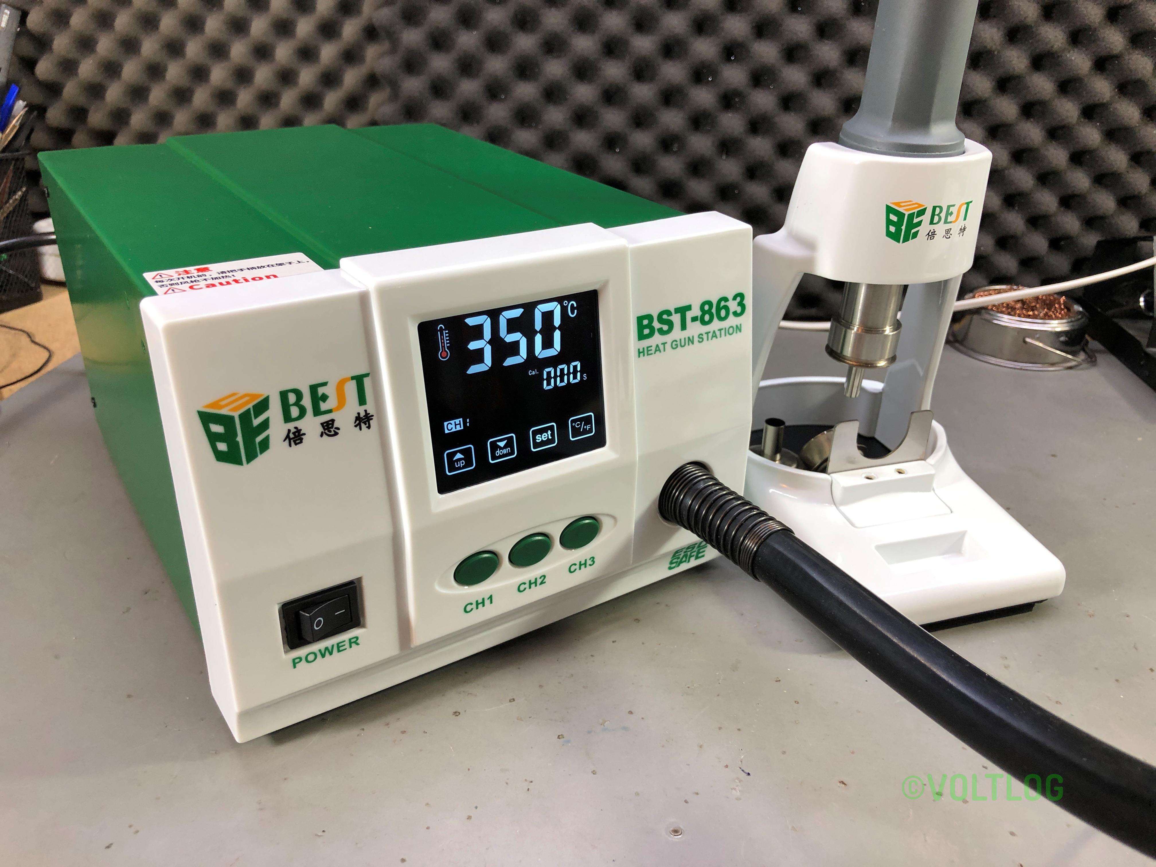
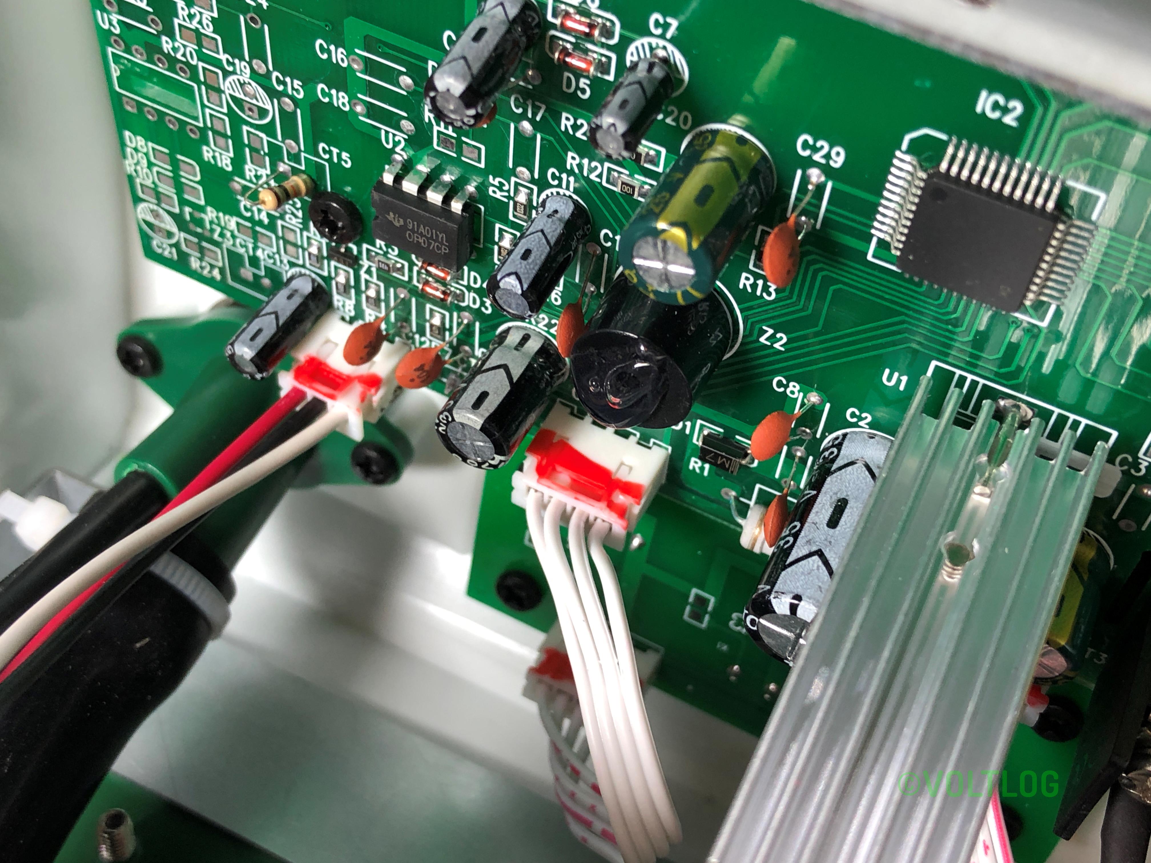
Voltlog #256 – Best BST-863 Hot Air Rework Station (Alternative to Quick 861DW)
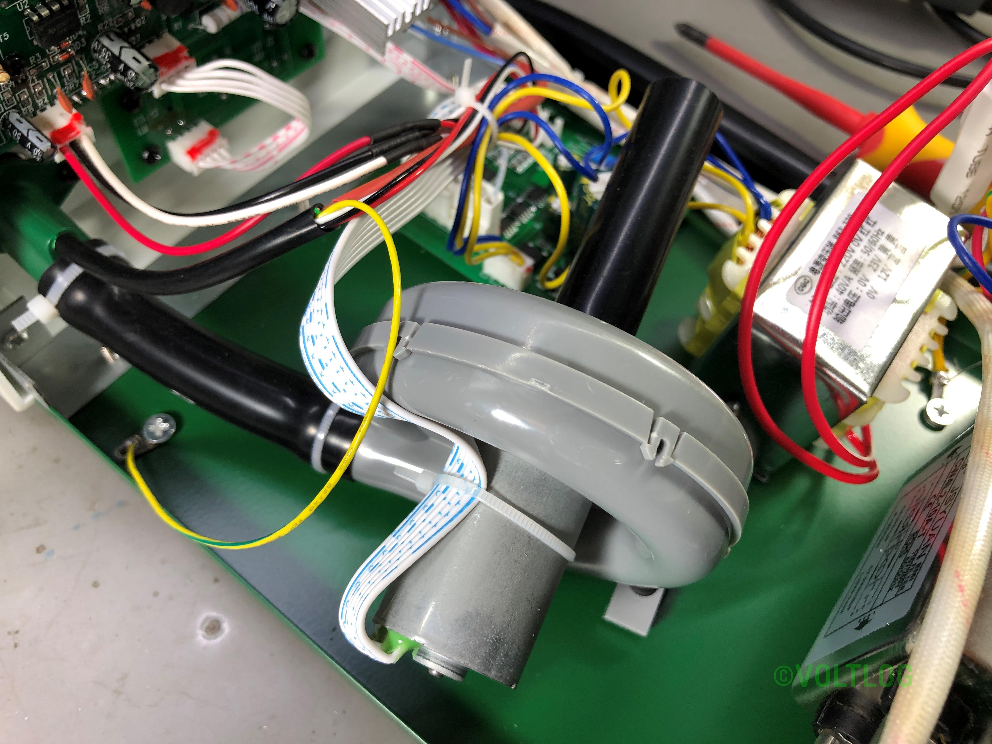
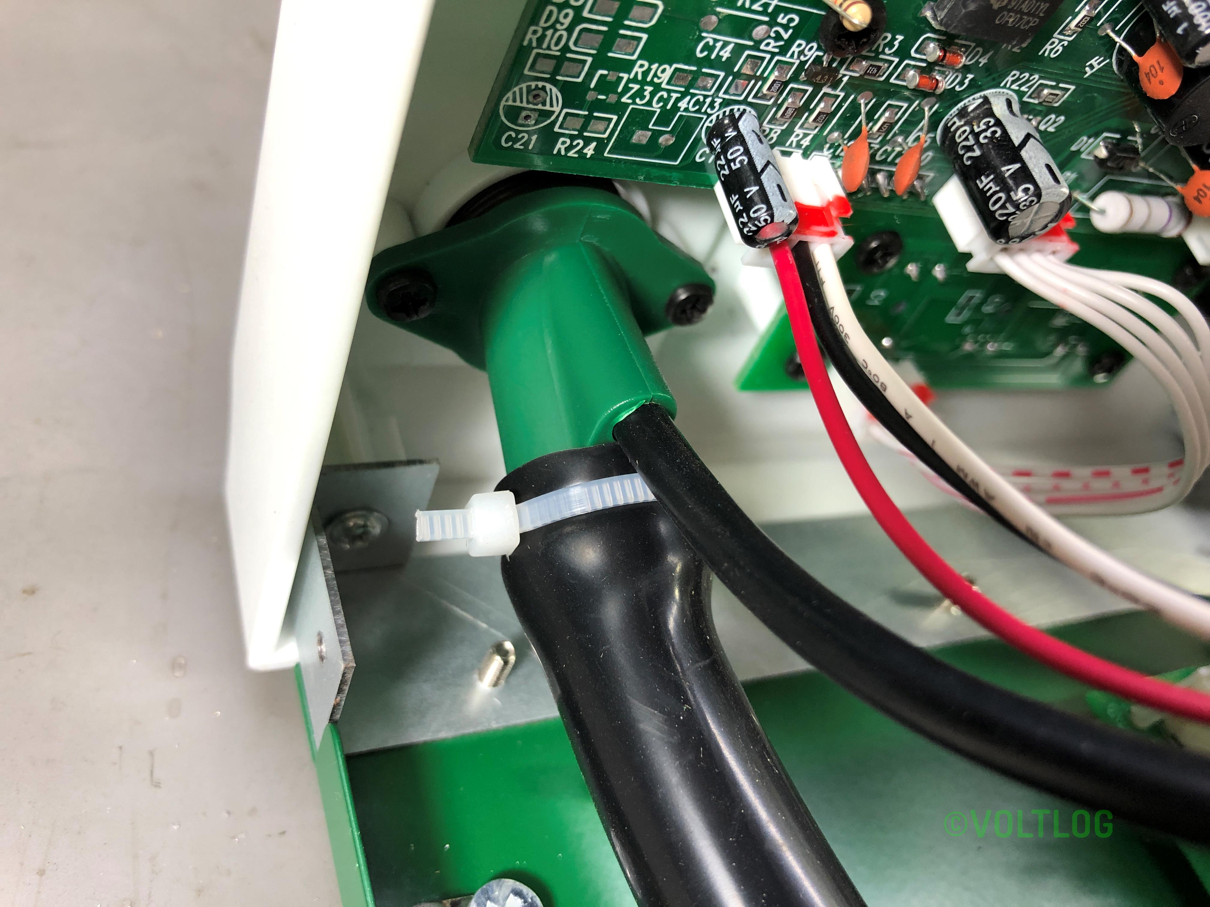
Inside the box of the BST-863 we have the station, a really nice and heavy stand for the tool piece, a total of 3 nozzles, a grounding strap and a power cord. The first thing I notice is the hose which pretty thick, certainly thicker than what I had on my old Gordak station but seems to be softer material. The way it’s designed with the tool standing vertically in the stand makes the air hose forms this loop which depending on your bench setup might or might not bother you but it’s something to consider. But I like the quality of the stand, it’s heavy and feels very sturdy, you get this accessory here which allows you to remove the nozzles while hot and the station has a sensor to detect when the handle is in the stand.
Adjustment of temperature and air level is made through this touch screen control. I’m a bit anti touch screen control on test gear so I would’ve preferred some switches on the front panel but don’t get me wrong, the touch screen works well on this unit, it has nice big touch keys and after setting up your presets you are likely not going to need to adjust the temperature you will just be using the presets like leaded, lead free and another one for heatshrink maybe.
Is this cheaper station a good alternative to the Quick 861DW? This video review should provide you with enough info to decide which one to buy.
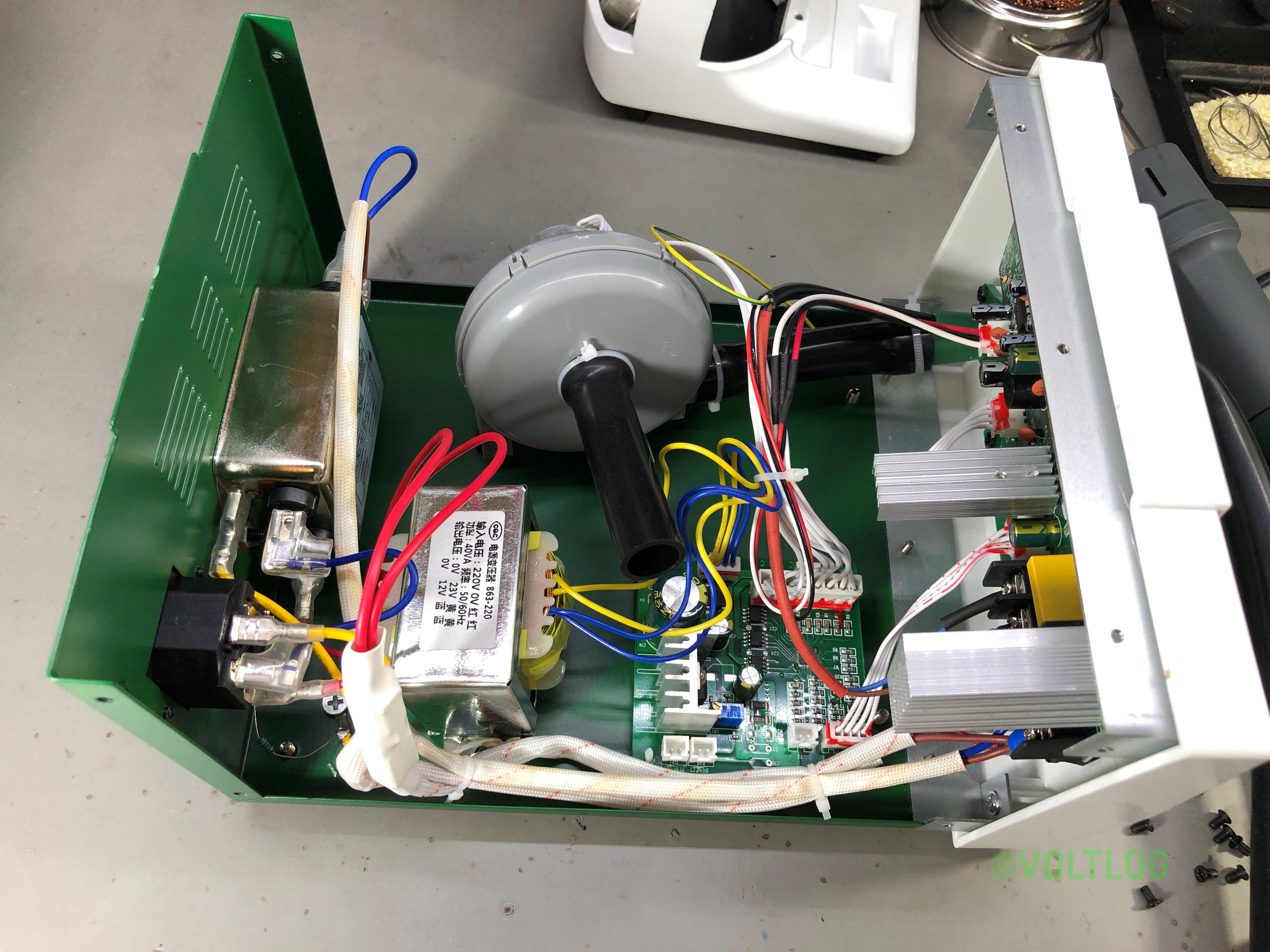
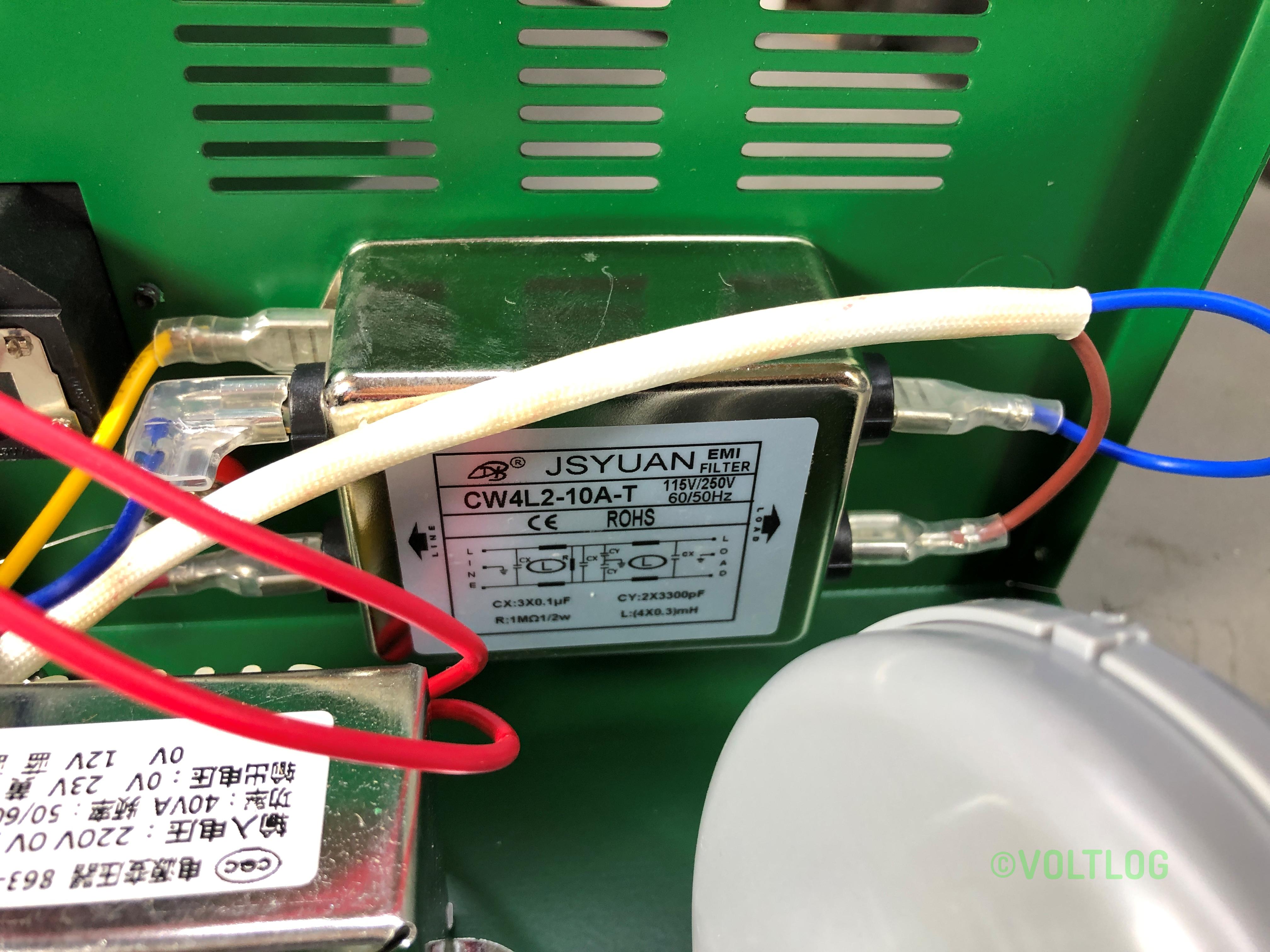
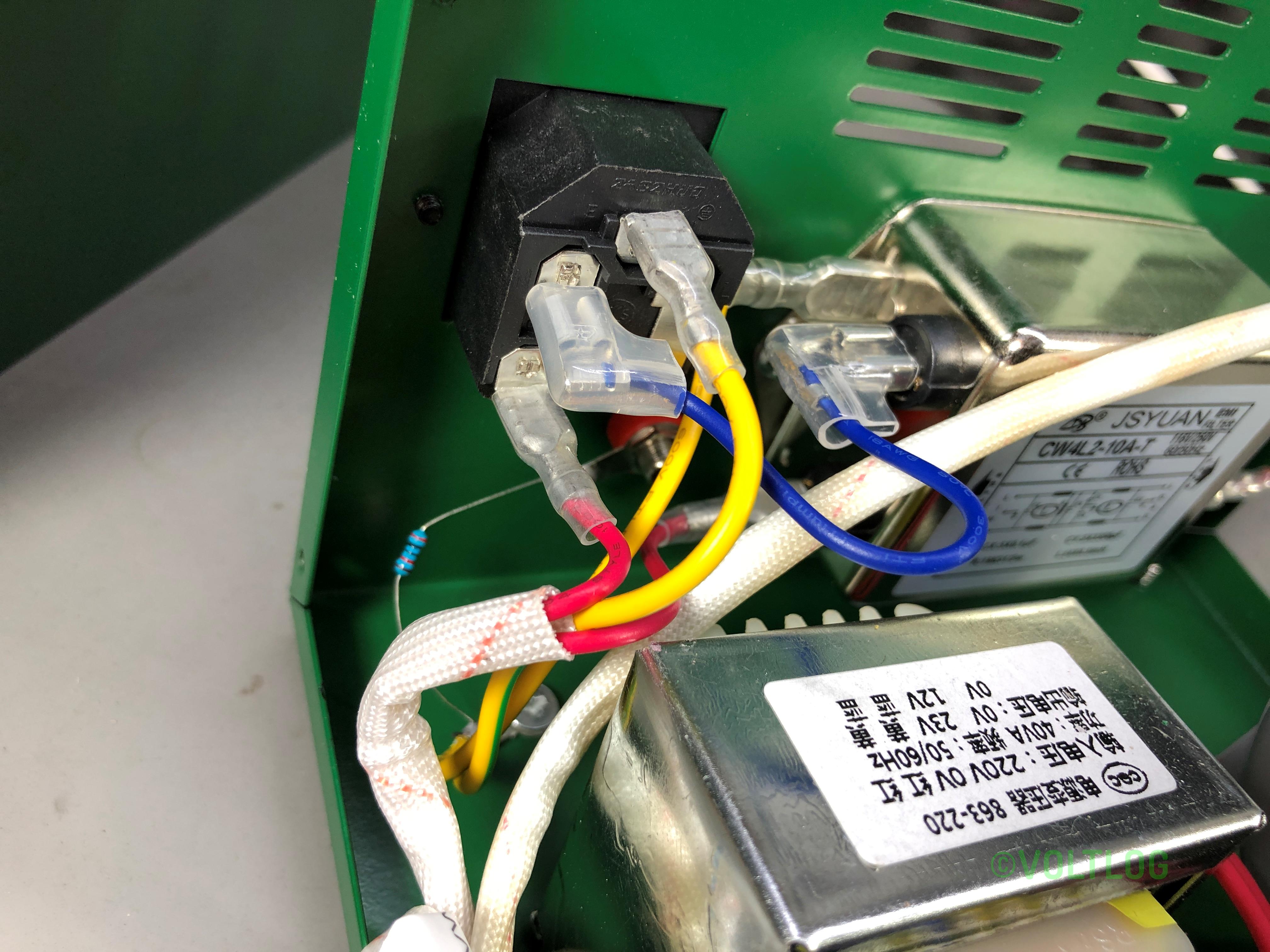
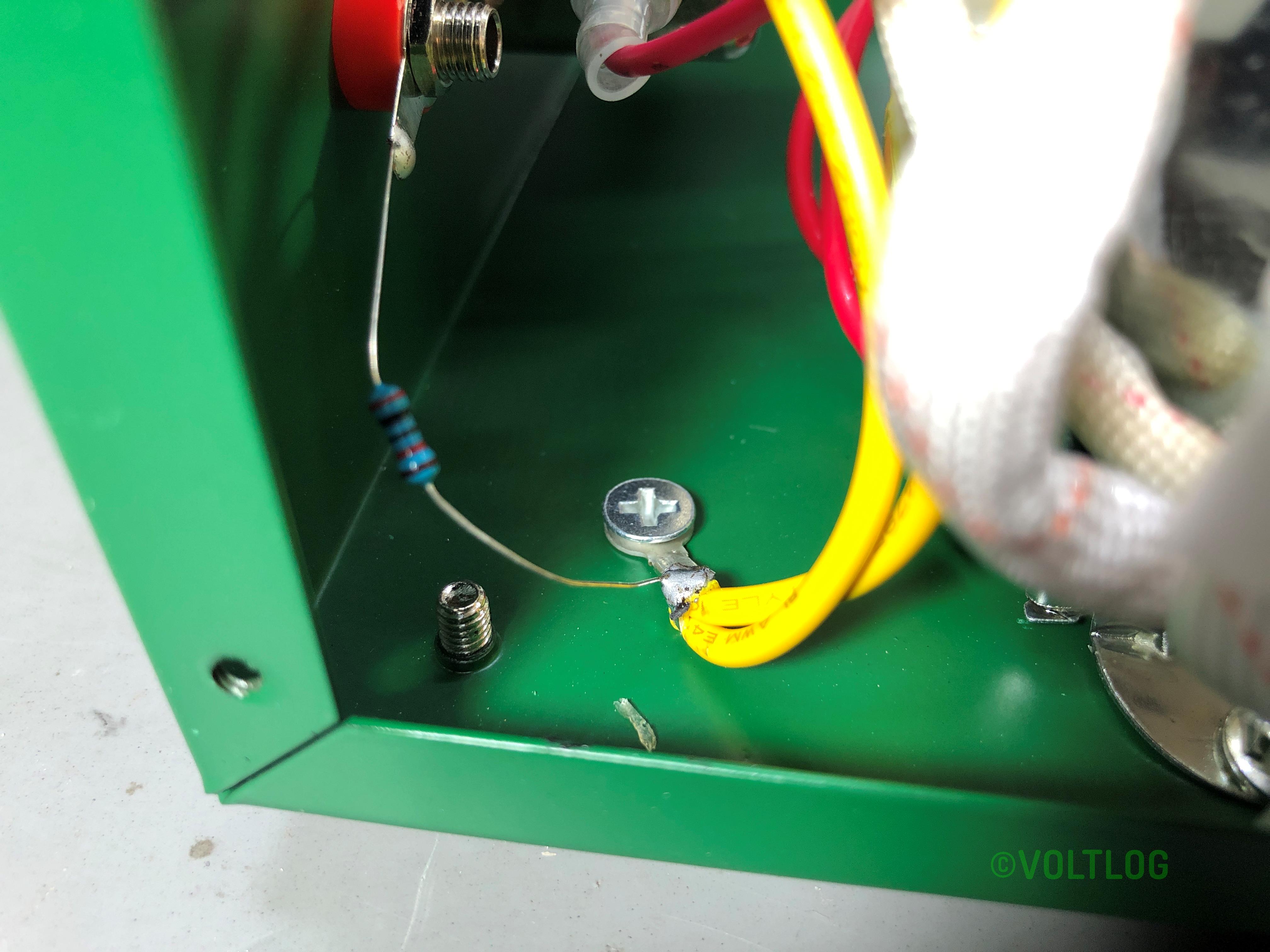
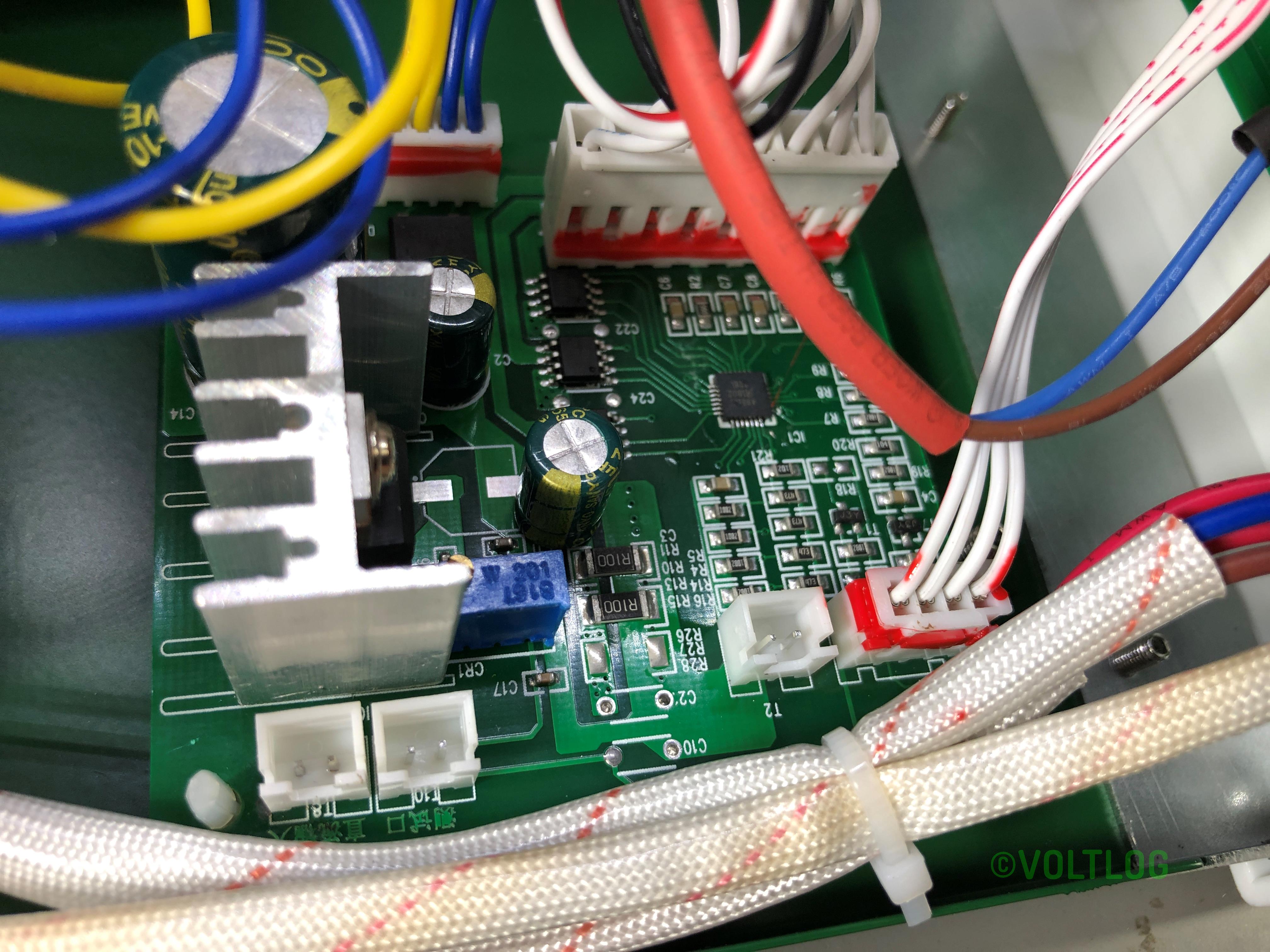
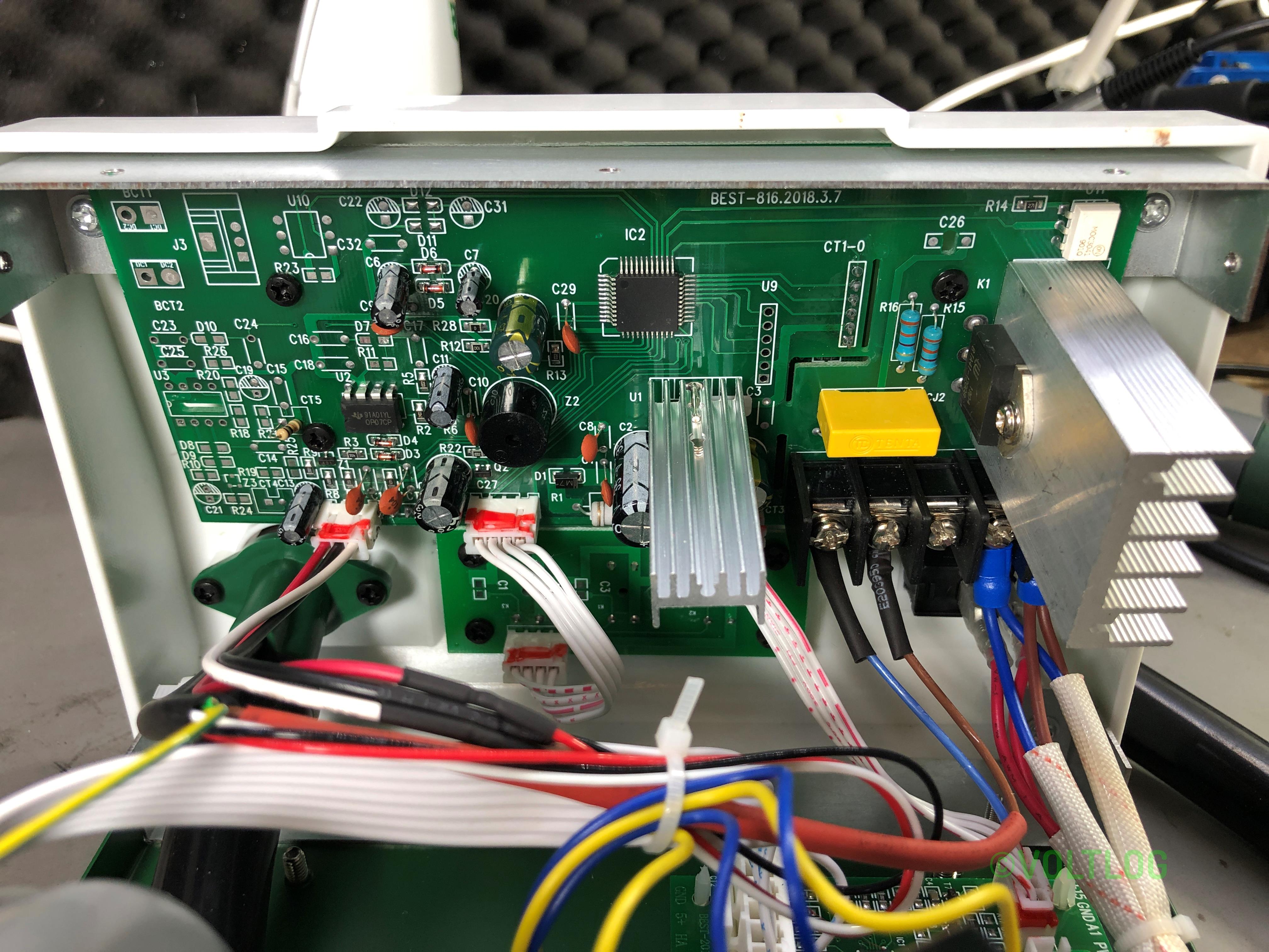
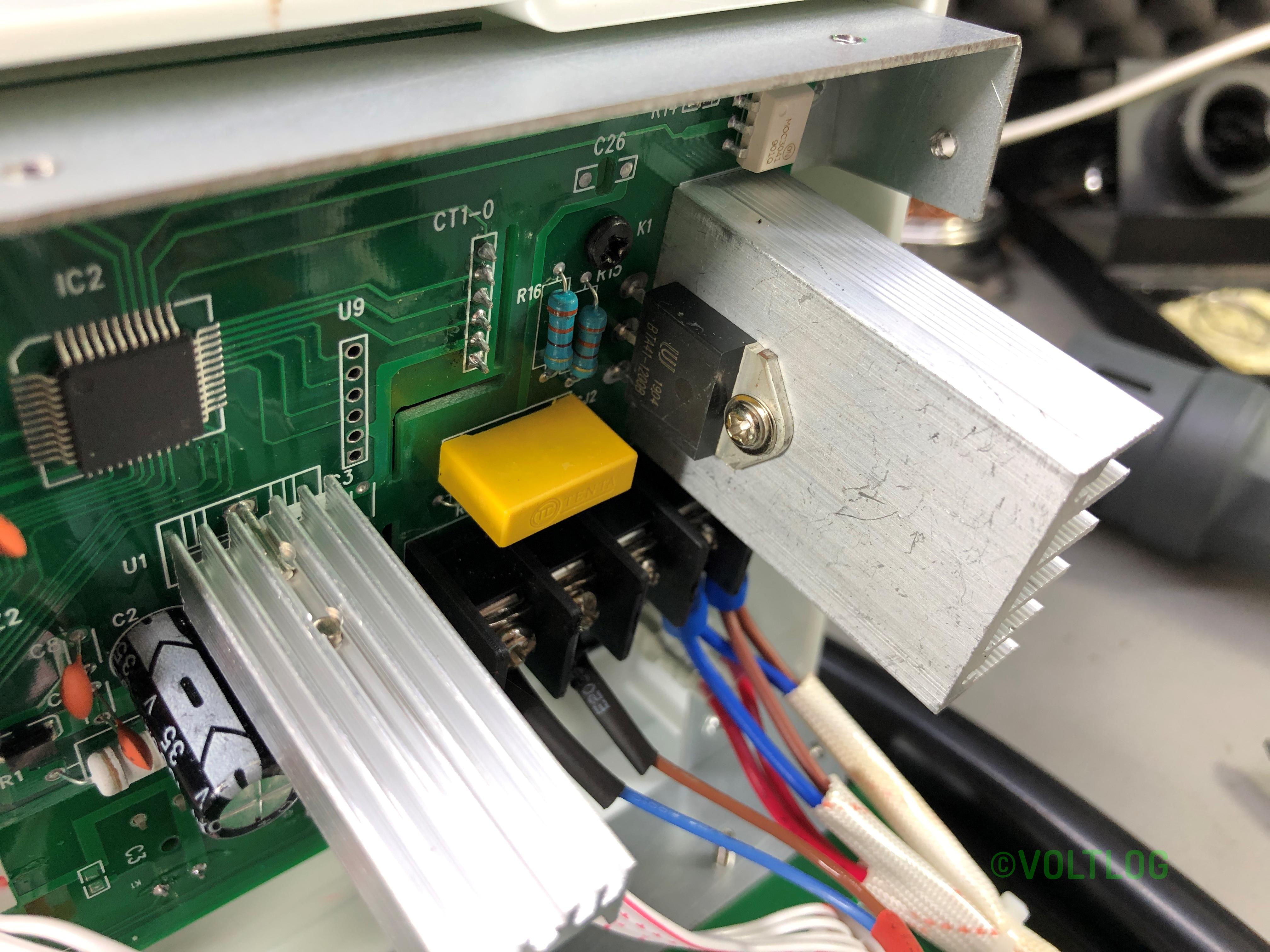
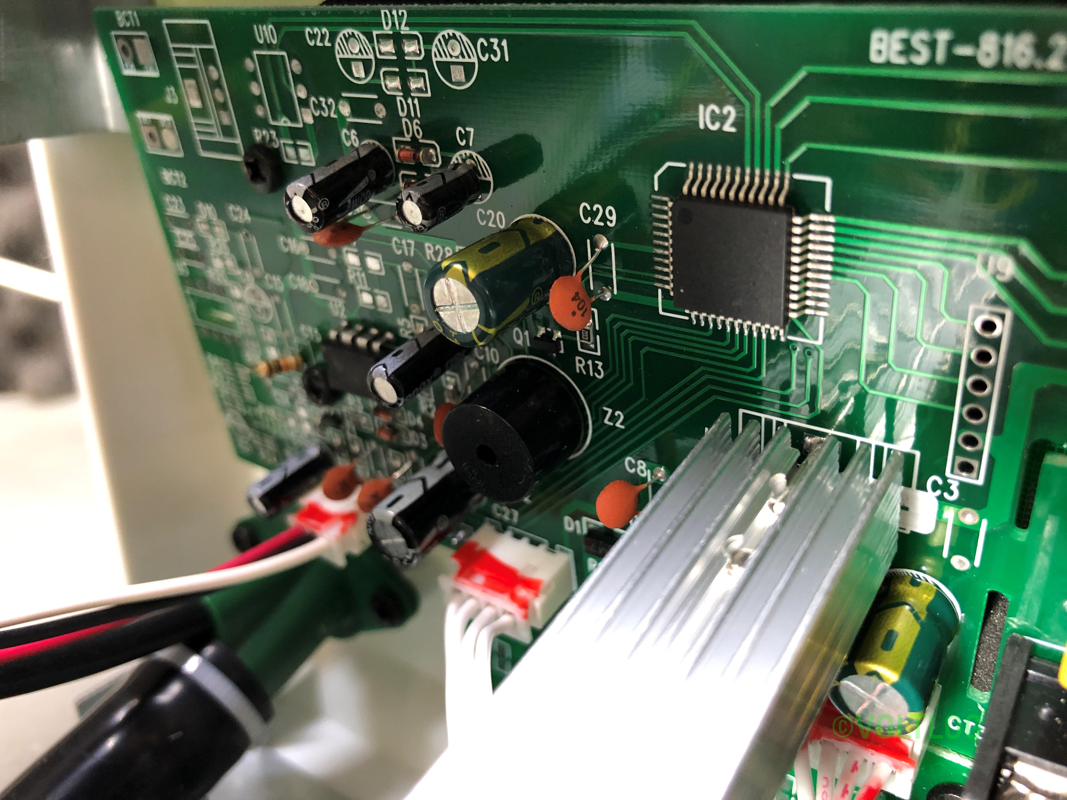
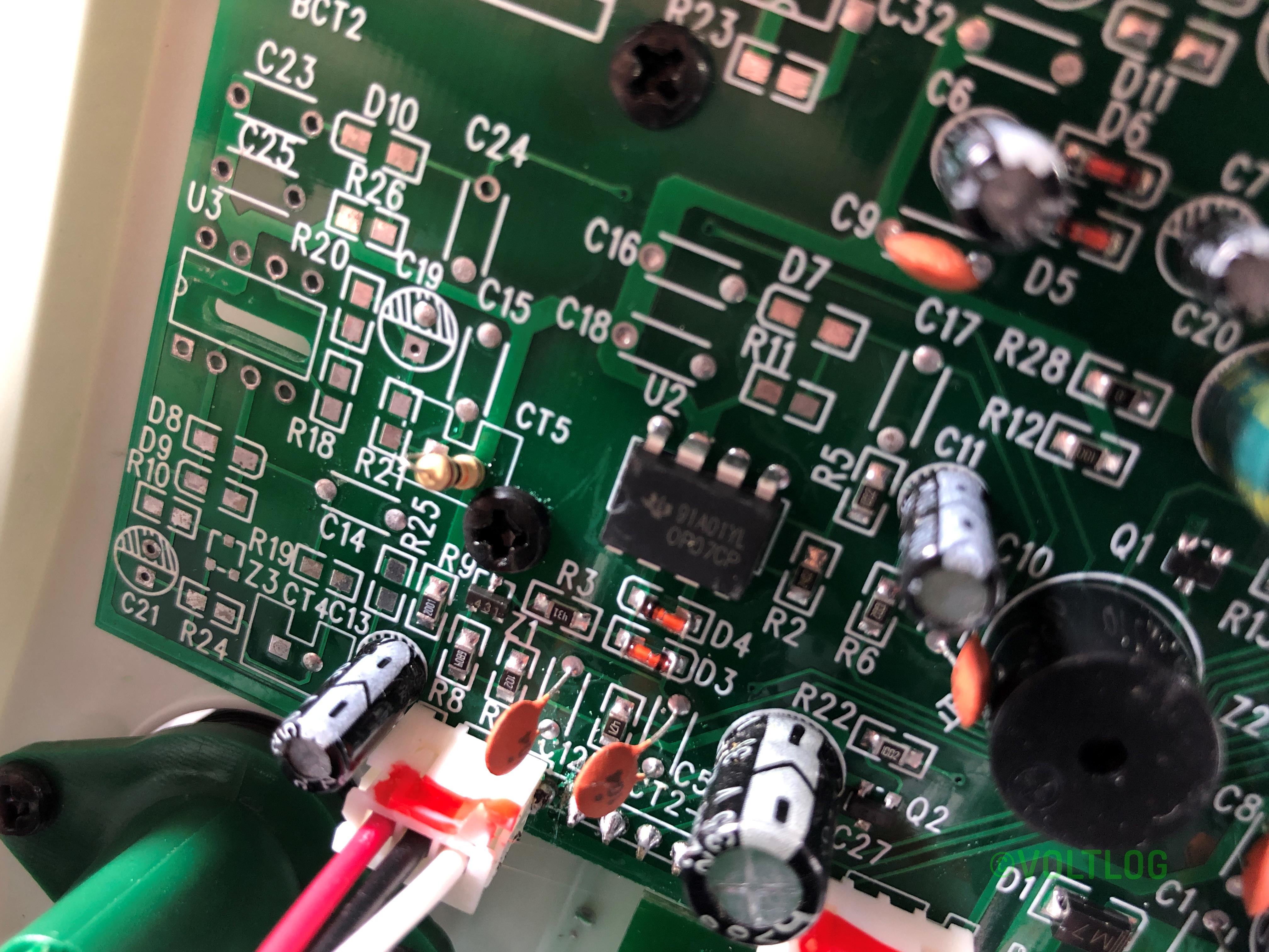
Here are some high resolution images from the teardown:
Voltlog #252 – How to fix a solder bridge
Welcome to a new Voltlog, today I want to talk about solder bridges and show you how to deal with them. A solder bridge can happen for many reasons, incorrect soldering temperature, incorrect amount of solder being used, too little or no flux, or just the incorrect technique for soldering but they all basically mean the same thing , a blob of solder shorting two or more conductive surfaces on your PCB.
Modern printed circuit boards which typically get soldermask coverage even between IC pins will help prevent this problem because molten solder normally doesn’t stick to the soldermask surface and so it’s harder to form a bridge across that surface.
But even with enough experience and the proper technique solder bridges can still happen if you do hand soldering on fine pitch ICs, it’s just part of the soldering job. It’s true that as you get better at soldering they will happen less often but don’t think they go away forever. So it’s good to know how to deal with them.
Voltlog #250 – Replacing Bad 4mm Banana Plugs With High Quality Hirschmann and Staubli
In this video I replace some of my old crappy 4mm banana connectors with some new Hirschmann and Staubli, high quality connectors. These should be more reliable and provide a low resistance connection between my test gear allowing me to pass high currents without any issue.
Voltlog #249 – Making Some USB Serial Converter Boards With CH340E (part 1)
Welcome to a new video, today I’m building a bunch of usb to serial converter boards because if you are into electronics and microcontrollers you will for sure need a bunch of usb to serial converters to connect your boards to a computer for example.
The idea for building these boards started when I found the CH340E converter chip on aliexpress, I like several things about this chip, it was small because it comes in MSOP10 package, it was cheap at about $0.40 a piece and it requires minimal external circuitry, in fact it only needs an external bypass cap.
Voltlog #243 – TS80 VS KSGER T12 Soldering Iron Comparison
Welcome to a new Voltlog, yet another soldering iron comparison video and today it’s between the TS80 and the KSGER T12 station. Everyone knows the TS80, is quite a popular portable soldering iron, works with USB type C input, it needs a quick charge compatible adapter to reach full power and it’s quite a capable soldering iron. The drawback is the cost of the tips, it uses this proprietary type of tip and the cost is about $20 a piece.
On the other hand we have the KSGER soldering station which I reviewed in Voltlog #232. This station has a built in power supply and uses the well known T12 tips which are widely available on aliexpress, for example you can get KSGER T12 branded tips for about $3 a piece. I think that’s important, because I have 2-3 different tip shapes that I use regularly and maybe another 2 or 3 that I use occasionally for odd jobs. You can’t just rely on a single tip shape and purchasing the same number of tips for the TS80, is not going to be cheap.
Voltlog #240 – ESP32 PIR Motion Sensor With Deep Sleep & MQTT
Welcome to a new Voltlog, in this video I’m gonna show you how I designed and built this board which functions as an esp32 based, battery powered PIR motion sensor. So I started by designing the circuit, I used some common building blocks, I added the ESP32 with it’s bypass caps, some test points and the programming circuit with auto-reset, I then added some connection points for the PIR sensor, an RGB LED because why not have a nice way to signal this is one of those very small digital RGB leds, it’s just 20x20mm, it’s connected to 3.3V even though it’s only rated for 5V so I’m hoping this is going to work even on 3.3, it’s also worth having a temperature/humidity sensor to also sense that in whichever room the node will be placed and finally the power supply circuit which is a simple low dropout regulator with an 18650 battery as the input.
I did not include a battery charger circuit on this module, because I wanted to keep things simple, I’ll have a battery socket so I can just remove the 18650 cell and charge it separately plus the whole circuit should run in sleep for extended periods of time giving me a long operating time so i wouldn’t have to charge the battery too often.
Once the schematic was finished I did the board layout in a hurry so it’s not exactly pretty or optimized
but I tried to move the esp32 antenna to the side, to place the PIR sensor in the top side as the module will probably sit vertically, I tried to place the temperature sensor in the bottom side to keep it away from any components that might get hot and also placed some isolation slots for the same reason.
You should check-out revB of this board, I made some improvements present in the video below.
Voltlog #234 – The Problems I Found With The KSGER T12 Soldering Station
In a previous Voltlog I reviewed this KSGER T12 soldering station, it was the first station I got my hands on from this manufacturer, it’s version 2.1S and I was pleasantly surprised by the features it has. If you haven’t seen that video I will link it on screen right now. Since then I’ve been using it as my main soldering station and I’ve been pretty happy with how it works but some of my viewers who have been using these for longer have pointed out a few things I missed in the video so this will be a quick update video to show the things I’ve missed previously.
Voltlog #230 – Guidelines For Board Level Temperature Sensor Layout & Placement
Welcome to a new Voltlog, today I’m gonna show you some techniques that you can use when doing temperature measurements. Typically you will want to measure either the ambient temperature or the system or component temperature. Depending on one of these goals you are going to follow different design rules to achieve that. And to better illustrate the problems, I have these 3 pcbs which have exactly the same electrical circuit but with different layouts on the pcb.
The boards consist of an esp8266 and a digital temperature sensor and you might expect that since all 3 boards are placed so close together, they should all indicate the same temperature but that is not the case as we can see on this graph we are getting 3 different temperatures and only one of them is close to the actual ambient temperature measured with another thermometer, so why is that happening? Well the answer lies in the layout of the PCB and that includes component placement, copper planes and various other elements on the PCB.